| DTC Code | DTC Name |
|---|---|
| C1432 | Steering Angle Sensor Power Source Voltage Malfunction |
DESCRIPTION
This DTC is stored when the skid control ECU (brake actuator assembly) receives a power supply open signal from the steering angle sensor.
| DTC No. | Detection Item | DTC Detection Condition | Trouble Area |
|---|---|---|---|
| C1432 | Steering Angle Sensor Power Source Voltage Malfunction | Steering angle sensor power supply malfunction signal is received from steering angle sensor. |
|
CAUTION / NOTICE / HINT
Inspect the fuses for circuits related to this system before performing the following procedure.
PROCEDURE
- Click here
CHECK HARNESS AND CONNECTOR (POWER SOURCE TERMINAL)
-
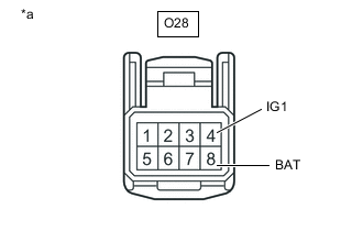
*a Front view of wire harness connector
(to Steering Angle Sensor)
Remove the steering wheel and column cover.
-
Make sure that there is no looseness at the locking part and the connecting part of the connector.
-
Disconnect the O28 steering angle sensor connector.
-
Measure the voltage according to the value(s) in the table below.
Standard Voltage Tester Connection Condition Specified Condition O28-8 (BAT) - Body ground Always 11 to 14 V O28-4 (IG1) - Body ground Engine switch on (IG) 11 to 14 V Result Proceed to OK NG
- OKClick here
- NG
REPAIR OR REPLACE HARNESS OR CONNECTOR (POWER SOURCE CIRCUIT)
-
- Click here
CHECK HARNESS AND CONNECTOR (GROUND TERMINAL)
-
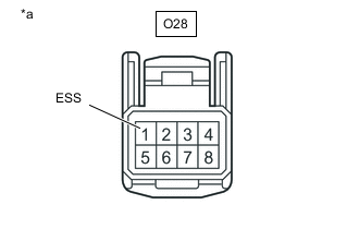
*a Front view of wire harness connector
(to Steering Angle Sensor)
Turn the engine switch off.
-
Measure the resistance according to the value(s) in the table below.
Note:Before measuring the resistance of the steering angle sensor, turn the engine switch off and leave the vehicle for 1 minute or more without operating the key or switches, or opening or closing the doors.
Standard Resistance Tester Connection Condition Specified Condition O28-1 (ESS) - Body ground 1 minute after turning engine switch off Below 1 Ω Result Proceed to OK NG Tip:If troubleshooting has been carried out according to Problem Symptoms Table, refer back to the table and proceed to the next step before replacing parts.
- OK
REPLACE STEERING ANGLE SENSORClick here
- NG
REPAIR OR REPLACE HARNESS OR CONNECTOR (GROUND CIRCUIT)
-