FUEL INJECTOR(for Port Injection) INSTALLATION

PROCEDURE
-
INSTALL FUEL INJECTOR ASSEMBLY
Tech Tips
Perform "Inspection After Repair" after replacing a fuel injector assembly.
-
w/ Canister Pump Module:
-
w/o Canister Pump Module:
-
Apply a light coat of spindle oil or gasoline to a new O-ring, and install one to each fuel injector assembly.
Note
Check that there is no damage or foreign matter on the groove of the fuel injector assembly when installing each O-ring to the fuel injector assembly.
-
Connect the 8 fuel injector assembly connector.
-
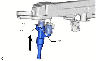
*a Claw *b Stopper Install the 8 fuel injector assemblies to the fuel delivery pipe sub-assembly and No. 2 fuel delivery pipe sub-assembly.
Note
-
Make sure that the fuel injector assembly is located within the stopper as shown in the illustration.
-
Check that there is no damage or foreign matter on the fuel injector assembly installation holes.
-
When installing the O-ring, make sure they do not become pinched or cut.
-
-
Engage the 3 clamps to connect the No. 6 engine wire to the fuel delivery pipe sub-assembly.
-
Engage the 3 clamps to connect the No. 7 engine wire to the No. 2 fuel delivery pipe sub-assembly.
-
-
INSTALL INJECTOR VIBRATION INSULATOR
-
Install 8 new injector vibration insulators to the intake air surge tank assembly.
-
-
INSTALL NO. 1 DELIVERY PIPE SPACER
-
Install the 4 No. 1 delivery pipe spacers to the intake air surge tank assembly.
-
-
INSTALL FUEL DELIVERY PIPE SUB-ASSEMBLY
-
Place the fuel delivery pipe sub-assembly with the fuel injector assemblies onto the intake air surge tank assembly.
Note
Be careful not to drop the fuel injector assemblies when installing the fuel delivery pipe sub-assembly.
-
Install the fuel delivery pipe sub-assembly with the fuel injector assemblies with the 2 bolts.
- Torque:
- 21 N*m { 214 kgf*cm, 15 ft.*lbf }
-
-
INSTALL NO. 2 FUEL DELIVERY PIPE SUB-ASSEMBLY
-
Place the No. 2 fuel delivery pipe sub-assembly with the fuel injector assemblies onto the intake air surge tank assembly.
Note
Be careful not to drop the fuel injector assemblies when installing the No. 2 fuel delivery pipe sub-assembly.
-
Install the No. 2 fuel delivery pipe sub-assembly with the fuel injector assemblies with the 2 bolts.
- Torque:
- 21 N*m { 214 kgf*cm, 15 ft.*lbf }
-
-
INSTALL FUEL TUBE SUB-ASSEMBLY
-
Install the fuel tube sub-assembly to the fuel delivery pipe sub-assembly and No. 2 fuel delivery pipe sub-assembly.
Note
Check if there is any damage or foreign matter on the connecting parts of the fuel pipe.
-
Align the fuel tube connector with the fuel pipe, and push them together until the fuel tube connector makes a "click" sound. If it is difficult to push the fuel pipe into the fuel tube connector, apply a small amount of clean engine oil to the tip of the fuel pipe and reinsert it.
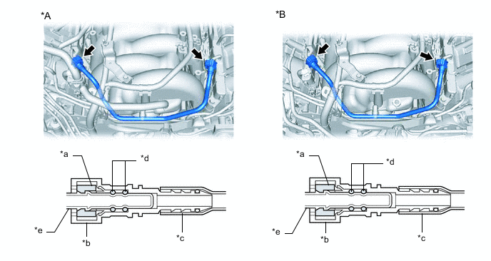
*A for LHD *B for RHD *a Retainer *b Fuel Tube Connector *c Nylon Tube *d O-ring *e Fuel Pipe - - -
After connecting the fuel pipes, check that the fuel pipe and fuel tube connector are securely connected by pulling on them.
-
-
Push in the fuel tube connector cover.
-
for LHD:
-
Install the wire harness bracket to the intake air surge tank assembly with the bolt.
- Torque:
- 10 N*m { 102 kgf*cm, 7 ft.*lbf }
-
Engage the clamp to connect the wire harness.
-
-
for RHD:
-
Install the wire harness bracket to the intake air surge tank assembly with the bolt.
- Torque:
- 10 N*m { 102 kgf*cm, 7 ft.*lbf }
-
Connect the union to check valve hose to the intake air surge tank assembly and slide the clip to secure it.
-
-
Install the wire harness bracket to the intake air surge tank assembly with the bolt.
- Torque:
- 10 N*m { 102 kgf*cm, 7 ft.*lbf }
-
-
INSTALL PURGE VALVE (PURGE VSV)
-
INSTALL WATER BY-PASS PIPE SUB-ASSEMBLY
-
INSTALL INJECTOR DRIVER BRACKET
-
INSTALL INJECTOR DRIVER
-
ENGAGE ENGINE WIRE
-
INSTALL FRONT SUSPENSION UPPER BRACE BRACKET
-
INSTALL FRONT SUSPENSION UPPER TO COWL BRACE RH
-
INSTALL FRONT SUSPENSION UPPER TO COWL BRACE LH
-
INSTALL THROTTLE BODY WITH MOTOR ASSEMBLY
-
CONNECT NO. 2 FUEL TUBE SUB-ASSEMBLY
-
Connect the No. 2 fuel tube sub-assembly to the fuel delivery pipe sub-assembly.
Note
Check if there is any damage or foreign matter on the connecting parts of the fuel lines.
-
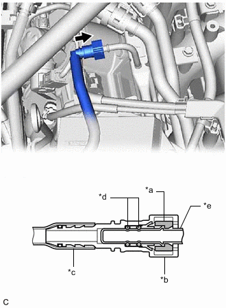
*a Retainer *b Fuel Tube Connector *c Nylon Tube *d O-ring *e Fuel Pipe 
Push Align the fuel tube connector with the fuel pipe, and push them together until the fuel tube connector makes a "click" sound. If it is difficult to push the fuel pipe into the fuel tube connector, apply a small amount of clean engine oil to the tip of the fuel pipe and reinsert it.
-
After connecting the fuel pipes, check that the fuel pipe and fuel tube connector are securely connected by pulling on them.
-
-
Install the EFI fuel pipe clamp to the fuel tube connector.
-
-
CONNECT CABLE TO NEGATIVE BATTERY TERMINAL
Note
When disconnecting the cable, some systems need to be initialized after the cable is reconnected.
-
INSPECT FOR FUEL LEAK
-
PERFORM INITIALIZATION
-
Perform "Inspection After Repair" after replacing a fuel injector assembly.
-
w/ Canister Pump Module:
-
w/o Canister Pump Module:
-
-