ENGINE UNIT REMOVAL

PROCEDURE
-
INSTALL ENGINE TO ENGINE STAND
-
Install the engine assembly to an engine stand with the bolts.
-
-
REMOVE NO. 1 ENGINE HANGER
-
Remove the 2 bolts and 2 No. 1 engine hangers.
-
-
REMOVE ENGINE WIRE
-
Remove the engine wire from the engine assembly.
-
-
REMOVE FRONT NO. 1 ENGINE MOUNTING BRACKET LH
-
Remove the 4 bolts and front No. 1 engine mounting bracket LH.
-
-
REMOVE FRONT NO. 1 ENGINE MOUNTING BRACKET RH
-
Remove the 4 bolts and front No. 1 engine mounting bracket RH.
-
-
REMOVE WIRE HARNESS CLAMP BRACKET
-
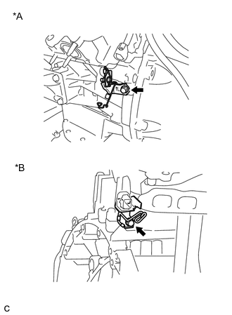
*A for LH Side *B for RH Side Remove the 2 bolts and 2 wire harness clamp brackets.
-
-
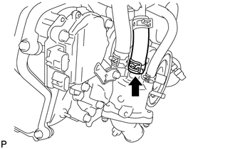
REMOVE TRANSMISSION BREATHER ASSEMBLY
-
REMOVE THROTTLE BODY WITH MOTOR ASSEMBLY
-
REMOVE INJECTOR DRIVER
-
REMOVE INJECTOR DRIVER BRACKET
-
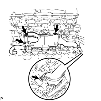
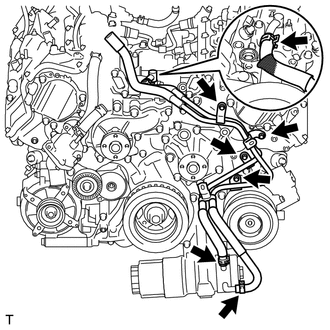
REMOVE WATER BY-PASS PIPE SUB-ASSEMBLY
-
Slide the clip and disconnect the No. 3 water by-pass hose from the water by-pass pipe sub-assembly.
-
Slide the clip and disconnect the water by-pass hose from the water by-pass pipe sub-assembly.
-
Slide the clip and disconnect the No. 5 water by-pass hose from the water by-pass pipe sub-assembly.
-
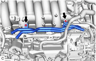
Remove the 2 bolts and water by-pass pipe sub-assembly from the intake air surge tank assembly.
-
-
REMOVE PURGE VALVE (PURGE VSV)
-
DISCONNECT VENTILATION HOSE
-
REMOVE FUEL TUBE SUB-ASSEMBLY
-
REMOVE NO. 2 FUEL DELIVERY PIPE SUB-ASSEMBLY (for Port Injection)
-
REMOVE FUEL DELIVERY PIPE SUB-ASSEMBLY (for Port Injection)
-
REMOVE NO. 1 DELIVERY PIPE SPACER
-
REMOVE INJECTOR VIBRATION INSULATOR
-
REMOVE FUEL INJECTOR ASSEMBLY (for Port Injection)
-
DISCONNECT NO. 1 FUEL PIPE SUB-ASSEMBLY
-
REMOVE INTAKE AIR SURGE TANK ASSEMBLY
-
REMOVE NO. 1 ENGINE COVER SUB-ASSEMBLY
-
REMOVE NO. 3 COVER SUB-ASSEMBLY
-
REMOVE NO. 1 FUEL PIPE SUB-ASSEMBLY
-
REMOVE NO. 3 FUEL PIPE SUB-ASSEMBLY
-
REMOVE NO. 2 FUEL PIPE SUB-ASSEMBLY
-
REMOVE FUEL PUMP WITH SEAL SUB-ASSEMBLY (for Bank 1)
-
REMOVE FUEL PUMP WITH SEAL SUB-ASSEMBLY (for Bank 2)
-
REMOVE NO. 2 ENGINE COVER SUB-ASSEMBLY LH
-
REMOVE NO. 4 FUEL PIPE SUB-ASSEMBLY
-
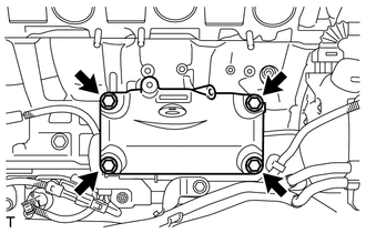
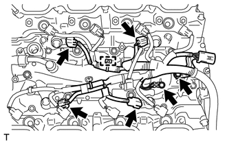
REMOVE CASE SEPARATOR
-
Disconnect the fuel pressure sensor connector.
-
Remove the 4 bolts and case separator from the cylinder head.
-
-
REMOVE FUEL DELIVERY PIPE LH
-
REMOVE FUEL DELIVERY PIPE RH
-
REMOVE FUEL INJECTOR ASSEMBLY (for Direct Injection)
-
REMOVE FUEL INJECTOR SEAL
-
REMOVE NO. 5 ENGINE WIRE
-
Disconnect the 4 knock sensor connectors.
-
Remove the 2 bolts and No. 5 engine wire.
-
-
REMOVE NO. 4 ENGINE COVER SUB-ASSEMBLY
-
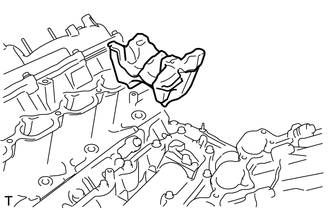
Remove the No. 4 engine cover sub-assembly.
-
-
REMOVE NO. 2 IDLER PULLEY SUB-ASSEMBLY
-
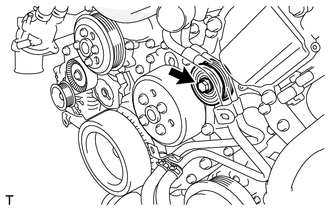
Remove the bolt and No. 2 idler pulley sub-assembly.
-
-
REMOVE OIL PUMP DRIVE SHAFT PULLEY
-
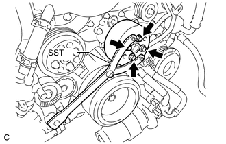
Using SST, hold the oil pump drive shaft pulley.
- SST
- 09960-10010
-
Remove the 4 bolts and oil pump drive shaft pulley.
-
-
REMOVE WATER PUMP PULLEY
-
REMOVE WATER INLET HOUSING
-
Slide the clip and disconnect the water inlet hose from the water inlet housing.
-
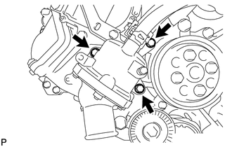
Remove the 3 bolts, water inlet housing and gasket.
-
-
REMOVE ENGINE OIL PRESSURE SWITCH ASSEMBLY
-
REMOVE ENGINE OIL TEMPERATURE SENSOR
-
REMOVE ENGINE OIL LEVEL SENSOR
-
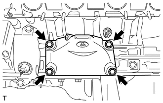
REMOVE NO. 2 WATER BY-PASS PIPE SUB-ASSEMBLY
-
Slide the 3 clips and disconnect the No. 2 water by-pass pipe sub-assembly from the oil cooler and heat exchanger assembly.
-
Remove the 4 bolts and No. 2 water by-pass pipe sub-assembly.
-
-
REMOVE ENGINE COOLANT TEMPERATURE SENSOR
-
REMOVE KNOCK CONTROL SENSOR
-
REMOVE IGNITION COIL ASSEMBLY
-
REMOVE NO. 4 V-BANK COVER BRACKET SUB-ASSEMBLY
-
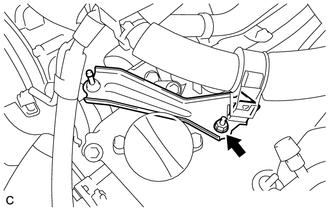
Remove the nut and No. 4 V-bank cover bracket sub-assembly.
-
-
REMOVE NO. 3 V-BANK COVER BRACKET SUB-ASSEMBLY
-
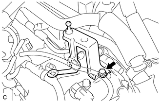
Remove the bolt and No. 3 V-bank cover bracket sub-assembly.
-