PROCEDURE
- Click here
REMOVE OIL FILLER CAP SUB-ASSEMBLY
-
Remove the oil filler cap sub-assembly from the oil filler cap housing.
-
Remove the oil filler cap gasket from the oil filler cap sub-assembly.
-
- Click here
REMOVE OIL FILLER CAP HOUSING
-
Remove the 2 bolts, oil filler cap housing and oil filler cap housing gasket.
-
- Click here
REMOVE SPARK PLUG
- Click here
REMOVE OIL PAN DRAIN PLUG
-
Remove the oil pan drain plug and gasket from the No. 2 oil pan sub-assembly.
-
- Click here
REMOVE VVT SENSOR (for Exhaust Side of Bank 1)
- Click here
REMOVE VVT SENSOR (for Exhaust Side of Bank 2)
- Click here
REMOVE VVT SENSOR (for Intake Side of Bank 1)
- Click here
REMOVE VVT SENSOR (for Intake Side of Bank 2)
- Click here
REMOVE CAMSHAFT POSITION SENSOR
- Click here
REMOVE CRANKSHAFT POSITION SENSOR
- Click here
REMOVE CAMSHAFT TIMING OIL CONTROL VALVE ASSEMBLY LH
- Click here
REMOVE CAMSHAFT TIMING OIL CONTROL VALVE ASSEMBLY RH
- Click here
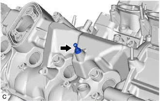
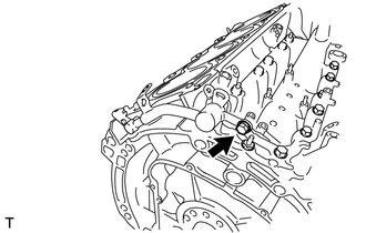
REMOVE CYLINDER BLOCK WATER DRAIN COCK SUB-ASSEMBLY
-
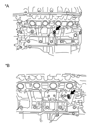
*A for Bank 1 *B for Bank 2 Remove the cylinder block water drain cock plug from each cylinder block water drain cock sub-assembly.
-
Remove each cylinder block water drain cock sub-assembly from the cylinder block sub-assembly.
-
- Click here
REMOVE CAMSHAFT TIMING CONTROL MOTOR WITH EDU ASSEMBLY LH
- Click here
REMOVE CAMSHAFT TIMING CONTROL MOTOR WITH EDU ASSEMBLY RH
- Click here
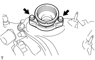
REMOVE FRONT WATER BY-PASS JOINT
-
Remove the 4 nuts, front water by-pass joint and 2 gaskets.
-
- Click here
REMOVE OIL FILTER CAP ASSEMBLY
-
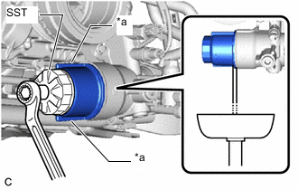
*a Cap Rib Using SST, loosen the oil filter cap assembly 4 turns, align the cap ribs vertically, and drain the remaining engine oil from the oil filter cap assembly.
09228-06501 Tip:Set a container below the oil filter cap assembly before loosening the oil filter cap assembly.
-
Remove the oil filter cap assembly.
-
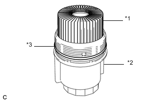
*1 Oil Filter Element *2 Oil Filter Cap Assembly *3 O-ring Remove the oil filter element and O-ring from the oil filter cap assembly.
Note:Do not use any tools to remove the O-ring in order to prevent the oil filter cap assembly from being damaged. Be sure to remove it by hand.
-
- Click here
REMOVE OIL THERMOSTAT HOUSING ASSEMBLY
- Click here
REMOVE OIL FILTER BRACKET
-
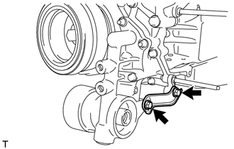
Remove the 2 bolts and oil filter bracket stay.
-
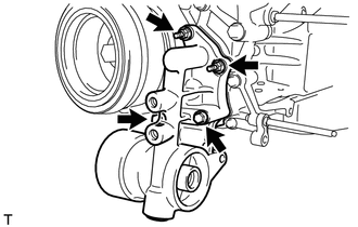
Remove the 2 bolts, 2 nuts and oil filter bracket.
-
Remove the 2 gaskets from the timing chain cover assembly.
-
- Click here
REMOVE CRANKSHAFT PULLEY
- Click here
REMOVE NO. 1 V-BANK COVER BRACKET (for Bank 1)
-
Remove the No. 1 V-bank cover bracket from the cylinder head cover sub-assembly LH.
-
- Click here
REMOVE NO. 1 V-BANK COVER BRACKET (for Bank 2)
-
Remove the No. 1 V-bank cover bracket from the cylinder head cover sub-assembly.
-
- Click here
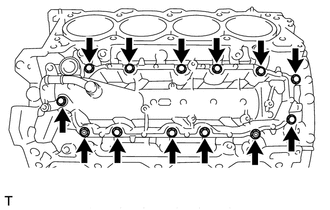
REMOVE CYLINDER HEAD COVER SUB-ASSEMBLY LH
-
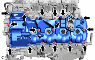
Remove the fuel pump spacer gasket.
-
Remove the 16 bolts, 3 seal washers, cylinder head cover sub-assembly LH and cylinder head cover gasket LH.
Tip:Arrange the removed parts in such a way that they can be installed to their original locations.
-
Remove the 2 oil hole gaskets and 2 O-rings from the camshaft bearing caps.
-
- Click here
REMOVE CYLINDER HEAD COVER SUB-ASSEMBLY
-
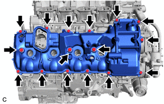
Remove the fuel pump spacer gasket.
-
Remove the 16 bolts, 3 seal washers, cylinder head cover sub-assembly and cylinder head cover gasket.
Tip:Arrange the removed parts in such a way that they can be installed to their original locations.
-
Remove the 2 oil hole gaskets and 2 O-rings from the camshaft bearing caps.
-
- Click here
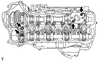
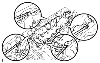
REMOVE SPARK PLUG TUBE GASKET
-
Using a screwdriver, pry out the 8 spark plug tube gaskets from each cylinder head sub-assembly and cylinder head LH.
Tip:Tape the screwdriver tip before use.
-
- Click here
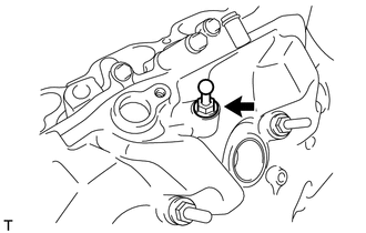
REMOVE OIL CONTROL VALVE FILTER LH
-
*1 Oil Control Valve Filter LH *2 Gasket *3 Cylinder Head Cover Spacer LH Remove the 2 bolts, cylinder head cover spacer LH and gasket.
-
Remove the oil control valve filter LH from the cylinder head cover spacer LH.
-
- Click here
REMOVE OIL CONTROL VALVE FILTER RH
-
*1 Oil Control Valve Filter RH *2 Gasket *3 Cylinder Head Cover Spacer RH Remove the 2 bolts, cylinder head cover spacer RH and gasket.
-
Remove the oil control valve filter RH from the cylinder head cover spacer RH.
-
- Click here
REMOVE V-RIBBED BELT TENSIONER ASSEMBLY
-
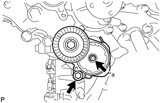
*a 6 mm Hexagon Bolt Remove the bolt, 6 mm hexagon bolt and V-ribbed belt tensioner assembly.
-
- Click here
REMOVE ENGINE WATER PUMP ASSEMBLY
-
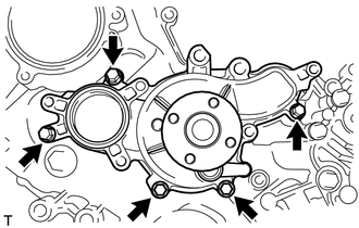
Remove the 5 bolts, engine water pump assembly and water pump gasket from the timing chain cover assembly.
-
- Click here
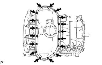
REMOVE TIMING CHAIN COVER ASSEMBLY
- Click here
REMOVE TIMING GEAR CASE OR TIMING CHAIN CASE OIL SEAL
- Click here
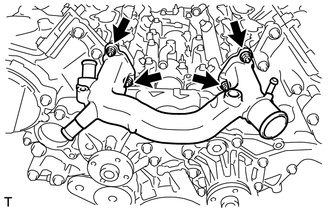
REMOVE INLET WATER PIPE
-
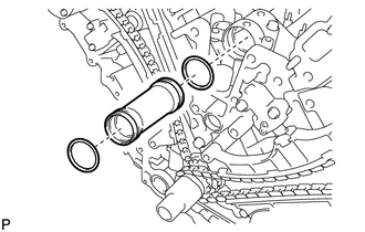
Remove the inlet water pipe.
-
Remove the 2 O-rings from the inlet water pipe.
-
- Click here
REMOVE NO. 1 OIL PIPE
- Click here
REMOVE NO. 2 OIL PIPE
- Click here
REMOVE NO. 3 OIL PIPE
- Click here
REMOVE SCAVENGING PUMP ASSEMBLY
- Click here
SET NO. 1 CYLINDER TO TDC / COMPRESSION
-
Temporarily tighten the crankshaft pulley set bolt.
-
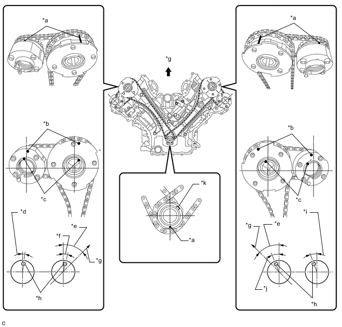
*a Timing Mark *b Timing Mark Position *c Knock Pin Position *d Approximately 2° *e Approximately 45° *f Approximately 16° *g Upward *h Timing Mark Position *i Approximately 20° *j Approximately 33° *k Key - - Rotate the crankshaft clockwise so that the timing marks on the crankshaft timing gear assembly and camshaft timing gears are as shown in the illustration.
Tip:If the timing marks do not align, rotate the crankshaft clockwise again and align the timing marks.
-
- Click here
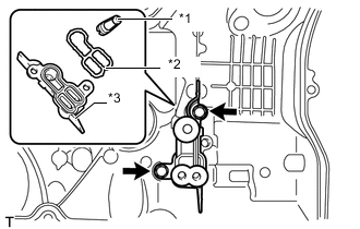
REMOVE NO. 1 CHAIN TENSIONER ASSEMBLY (for Bank 1)
-
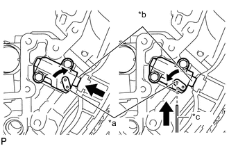
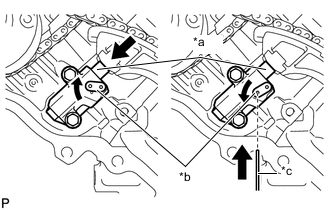
*a Stopper Plate *b Plunger *c Pin Turn the stopper plate clockwise to release the lock, and fully push the plunger into the No. 1 chain tensioner assembly.
-
Turn the stopper plate counterclockwise to set the lock, and insert a pin into the stopper plate hole.
-
Remove the 2 bolts and No. 1 chain tensioner assembly.
-
Remove the chain tensioner gasket.
-
- Click here
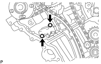
REMOVE CHAIN TENSIONER SLIPPER (for Bank 1)
-
Remove the chain tensioner slipper.
-
- Click here
REMOVE NO. 1 CHAIN VIBRATION DAMPER (for Bank 1)
-
Remove the 2 bolts and No. 1 chain vibration damper.
-
- Click here
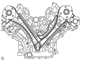
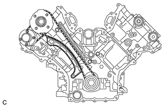
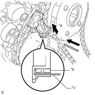
REMOVE CHAIN SUB-ASSEMBLY (for Bank 1)
-
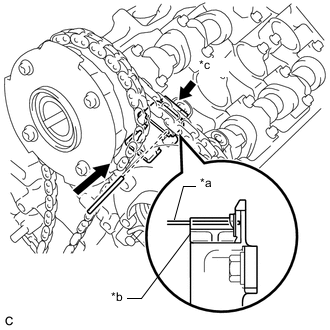
*a Pin *b Plunger *c Push While pushing down the No. 3 chain tensioner assembly, insert a pin of 1.0 mm (0.0394 in.) diameter into the hole to secure it in place.
-
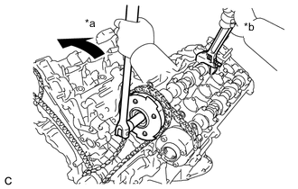
*a Hold *b Turn Using a wrench, hold the hexagonal portion of the camshaft and loosen the bolt with a 12 mm hexagon socket wrench.
Note:
-
Be careful not to damage the cylinder head with the wrench.
-
Do not disassemble the camshaft timing gear assembly.
-
-
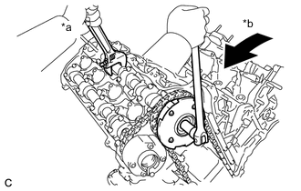
*a Hold *b Turn Using a wrench, hold the hexagonal portion of the camshaft and loosen the bolt with a wrench.
Note:Be careful not to damage the cylinder head with the wrench.
-
Remove the 2 bolts. Then with the chain sub-assembly and No. 2 chain sub-assembly still attached to the gears, remove the camshaft timing gear assembly, camshaft timing exhaust gear and crankshaft timing sprocket LH.
-
Remove the chain sub-assembly and No. 2 chain sub-assembly from the gears.
-
- Click here
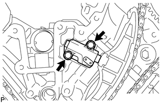
REMOVE NO. 3 CHAIN TENSIONER ASSEMBLY
-
Remove the 2 bolts and No. 3 chain tensioner assembly.
-
- Click here
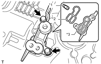
REMOVE NO. 1 CHAIN TENSIONER ASSEMBLY (for Bank 2)
-
*a Plunger *b Stopper Plate *c Pin Turn the stopper plate clockwise to release the lock, and fully push the plunger into the tensioner.
-
Turn the stopper plate counterclockwise to set the lock, and insert a pin of 1.0 mm (0.0394 in.) diameter into the stopper plate hole.
-
Remove the 2 bolts and No. 1 chain tensioner assembly.
-
- Click here
REMOVE CHAIN TENSIONER SLIPPER (for Bank 2)
-
Remove the chain tensioner slipper.
-
- Click here
REMOVE NO. 1 CHAIN VIBRATION DAMPER (for Bank 2)
-
Remove the 2 bolts and No. 1 chain vibration damper.
-
- Click here
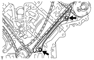
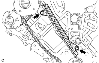
REMOVE CHAIN SUB-ASSEMBLY (for Bank 2)
-
*a Push *b Plunger *c Pin While pushing up the No. 2 chain tensioner assembly, insert a pin of 1.0 mm (0.0394 in.) diameter into the hole to secure it in place.
-
*a Hold *b Turn Using a wrench, hold the hexagonal portion of the camshaft and loosen the bolt with a 12 mm hexagon socket wrench.
Note:
-
Be careful not to damage the cylinder head with the wrench.
-
Do not disassemble the camshaft timing gear assembly.
-
-
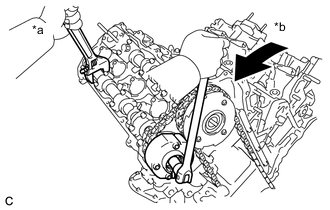
*a Hold *b Turn Using a wrench, hold the hexagonal portion of the camshaft and loosen the bolt with a wrench.
Note:Be careful not to damage the cylinder head with the wrench.
-
Remove the 2 bolts. Then with the chain sub-assembly and No. 2 chain sub-assembly still attached to the gears, remove the camshaft timing gear assembly, camshaft timing exhaust gear and crankshaft timing gear.
-
Remove the chain sub-assembly and No. 2 chain sub-assembly from the gears.
-
- Click here
REMOVE NO. 2 CHAIN TENSIONER ASSEMBLY
-
Remove the 2 bolts and No. 2 chain tensioner assembly.
-
- Click here
REMOVE CRANKSHAFT TIMING GEAR KEY
-
Using a screwdriver, remove the 2 crankshaft timing gear keys from the crankshaft.
-
- Click here
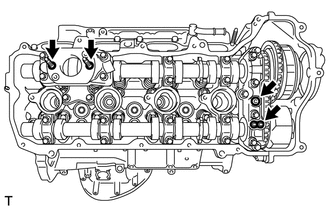
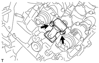
REMOVE OIL REFLECTOR PLATE LH
-
Remove the 2 bolts and oil reflector plate LH from the cylinder head LH.
-
- Click here
REMOVE CAMSHAFT BEARING CAP (for Bank 1)
- Click here
REMOVE NO. 3 CAMSHAFT SUB-ASSEMBLY
- Click here
REMOVE NO. 4 CAMSHAFT SUB-ASSEMBLY
- Click here
REMOVE OIL REFLECTOR PLATE RH
-
Remove the 2 bolts and oil reflector plate RH from the cylinder head sub-assembly.
-
- Click here
REMOVE CAMSHAFT BEARING CAP (for Bank 2)
- Click here
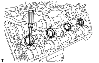
REMOVE CAMSHAFT
- Click here
REMOVE NO. 2 CAMSHAFT
- Click here
REMOVE NO. 1 VALVE ROCKER ARM SUB-ASSEMBLY
-
*1 Valve Adjusting Shim *2 Cylinder Head Valve Rocker Arm Pivot Remove the 32 No. 1 valve rocker arm sub-assemblies from the cylinder head LH and cylinder head sub-assembly.
Tip:Arrange the removed parts in such a way that they can be installed to their original locations.
-
- Click here
REMOVE CYLINDER HEAD VALVE ROCKER ARM PIVOT LH
-
Remove the 16 cylinder head valve rocker arm pivots LH from the cylinder head LH.
-
- Click here
REMOVE CYLINDER HEAD VALVE ROCKER ARM PIVOT RH
-
Remove the 16 cylinder head valve rocker arm pivots RH from the cylinder head sub-assembly.
-
- Click here
REMOVE CYLINDER HEAD SUB-ASSEMBLY
- Click here
REMOVE CYLINDER HEAD GASKET
- Click here
REMOVE CYLINDER HEAD LH
- Click here
REMOVE NO. 2 CYLINDER HEAD GASKET
- Click here
REMOVE CYLINDER BLOCK WATER JACKET SPACER
-

Remove the 2 cylinder block water jacket spacers from the cylinder block sub-assembly.
Note:Be sure to remove the cylinder block water jacket spacers. Otherwise, they may fall out and be damaged when the cylinder block is inverted.
-
- Click here
REMOVE HEAT EXCHANGER ASSEMBLY
-
Remove the bolt.
-
Remove the 11 bolts and 2 nuts.
-
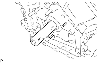
Remove the heat exchanger assembly by prying between the heat exchanger assembly and cylinder block sub-assembly with a screwdriver.
Tip:Tape the screwdriver tip before use.
-
- Click here
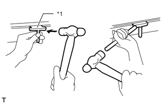
REMOVE VENTILATION PIPE GASKET
-

Using a screwdriver, pry out the ventilation pipe gasket.
Tip:Tape the screwdriver tip before use.
-
- Click here
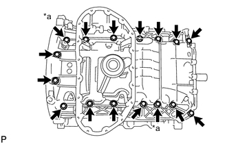
REMOVE NO. 2 OIL PAN SUB-ASSEMBLY
-
*a Nut Remove the 15 bolts and 2 nuts.
-
*1 Oil Pan Seal Cutter Insert the blade of an oil pan seal cutter between the oil pan sub-assembly and No. 2 oil pan sub-assembly. Cut through the applied sealer and remove the No. 2 oil pan sub-assembly.
Note:Be careful not to damage the contact surfaces of the oil pan sub-assembly and No. 2 oil pan sub-assembly.
-
- Click here
REMOVE OIL PAN SUB-ASSEMBLY
-
*a Nut Remove the 14 bolts and 2 nuts.
Tip:Be sure to clean the bolts and stud bolts and check the threads for cracks or other damage.
-
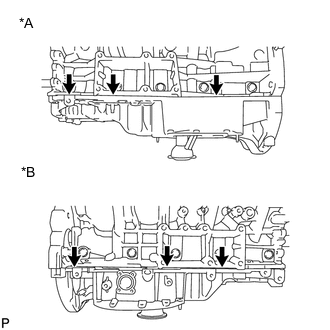
*A for Bank 1 Side *B for Bank 2 Side Remove the oil pan sub-assembly by prying between the oil pan sub-assembly and cylinder block with a screwdriver.
Note:Be careful not to damage the contact surfaces of the cylinder block and oil pan sub-assembly.
Tip:Tape the screwdriver tip before use.
-
- Click here
REMOVE NO. 1 OIL PAN BAFFLE PLATE
-
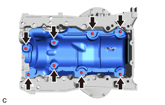
Remove the 8 bolts and No. 1 oil pan baffle plate.
-
- Click here
REMOVE OIL STRAINER SUB-ASSEMBLY
-
Remove the 2 bolts, oil strainer sub-assembly and O-ring.
-
- Click here
REMOVE ENGINE REAR OIL SEAL RETAINER
-
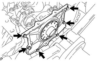
Remove the 6 bolts.
-
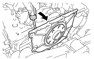
*a Protective Tape Using a screwdriver, pry out the engine rear oil seal retainer.
Note:Be careful not to damage the engine rear oil seal retainer and cylinder block sub-assembly.
Tip:Tape the screwdriver tip before use.
-
- Click here
REMOVE ENGINE REAR OIL SEAL
-
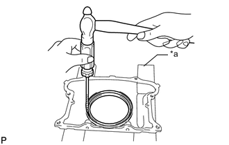
*a Wooden Block Place the engine rear oil seal retainer on wooden blocks.
-
Using a screwdriver and hammer, tap out the engine rear oil seal.
-
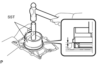
Using SST, tap in a new engine rear oil seal until its surface is flush with the engine rear oil seal retainer edge.
09223-15030 09950-70010 Note:
-
Keep the lip free from foreign matter.
-
Do not tap in the engine rear oil seal at an angle.
-
-
- Click here
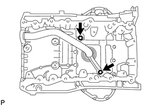
REMOVE OIL DRAIN PIPE SUB-ASSEMBLY
-
Remove the bolt and oil drain pipe sub-assembly.
-
Remove the O-ring from the oil drain pipe sub-assembly.
-