REAR CRANKSHAFT OIL SEAL INSTALLATION

PROCEDURE
-
INSTALL ENGINE REAR OIL SEAL
-
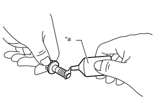
Apply MP grease to the lip of a new engine rear oil seal.
-
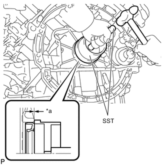
*a Oil Seal Protrusion Height Using SST and a hammer, tap in the engine rear oil seal.
- SST
- 09223-15030
Oil Seal Protrusion Height -0.5 to 0.5 mm (-0.0197 to 0.0197 in.) Note
-
Keep the lip free from foreign matter.
-
Do not tap in the engine rear oil seal at an angle.
-
Do not tap in the engine rear oil seal excessively.
-
-
INSTALL DRIVE PLATE AND RING GEAR SUB-ASSEMBLY
-
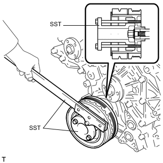
Using SST, hold the crankshaft pulley.
- SST
- 09330-00021 ( 09213-70020 )
-
Clean the 10 bolts and 10 bolt holes.
-
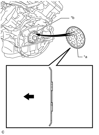
*a Pin Hole *b Pin 
Engine Front Install the crankshaft angle sensor rotor.
Tech Tips
Align the pin hole of the crankshaft angle sensor rotor with the pin of the crankshaft.
-
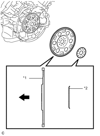
*1 Drive Plate *2 Rear Drive Plate Spacer Automatic Transmission Side Install the drive plate and ring gear sub-assembly and rear drive plate spacer on to the crankshaft.
Tech Tips
As the drive plate and ring gear sub-assembly and the rear drive plate spacer are not reversible, be sure to install them so that they are facing in the direction shown in the illustration.
-
*a Adhesive Apply a few drops of adhesive to 2 or 3 threads at the tip of each of the 10 bolts.
Adhesive Toyota Genuine Adhesive 1324, Three Bond 1324 or equivalent Note
Install the bolt within 3 minutes of applying adhesive.
-
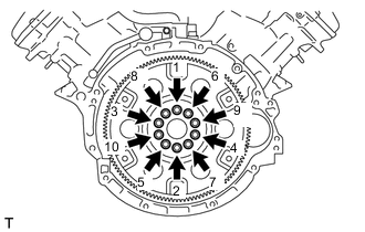
Install and uniformly tighten the 10 new bolts in the sequence shown in the illustration.
- Torque:
- 29.5 N*m { 301 kgf*cm, 22 ft.*lbf }
Note
Do not start the engine for at least 1 hour after installing the drive plate and ring gear sub-assembly.
-
Mark the upside of each drive plate and ring gear sub-assembly installation bolt with paint.
-
Tighten the drive plate and ring gear sub-assembly installation bolts another 90° as shown in the illustration.
-
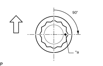
*a Paint Mark 
Up Check that the paint marks are now at 90° angle.
-
-
INSPECT DRIVE PLATE
-
INSTALL AUTOMATIC TRANSMISSION ASSEMBLY
-
INSPECT FOR ENGINE OIL LEAK