PROCEDURE
- Click here
INSPECT CYLINDER HEAD SET BOLT
- Click here
INSTALL CYLINDER HEAD GASKET
-
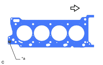
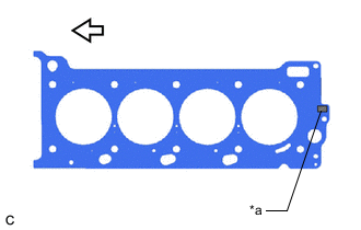
*a Lot No. 
Engine Front Place a new cylinder head gasket on the cylinder block sub-assembly with the Lot No. stamp facing upward.
Note:
-
Be sure to place the gasket in the correct orientation.
-
Gently lower the cylinder head sub-assembly in order not to damage the cylinder head gasket with the bottom of the cylinder head sub-assembly.
-
-
- Click here
INSTALL CYLINDER HEAD SUB-ASSEMBLY
-
Place the cylinder head sub-assembly on the cylinder block sub-assembly.
Note:
-
Clean all contact surfaces.
-
Inspect and clean each cylinder head set bolt and bolt hole.
-
Gently place the cylinder head sub-assembly in order not to damage the cylinder head gasket with the bottom part of the cylinder head sub-assembly.
-
-
Apply a light coat of engine oil to the threads and under the heads of the cylinder head set bolts.
Tip:The cylinder head set bolts are tightened in 3 progressive steps.
-
Step 1:
-
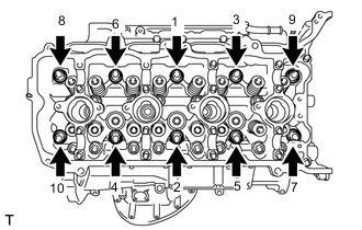
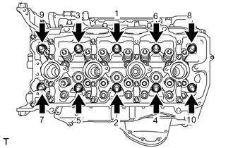
Using a 10 mm bi-hexagon wrench, install and uniformly tighten the 10 cylinder head set bolts with the plate washers in several steps in the order shown in the illustration.
36 N*m 367 kgf*cm 27 ft.*lbf
-
-
Step 2:
-
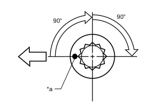
*a Paint Mark Engine Front Mark each cylinder head set bolt head with paint as shown in the illustration.
-
Tighten the cylinder head set bolts another 90° in the order shown in step 1.
-
-
Step 3:
-
Tighten the cylinder head set bolts by an additional 90° in the order shown in step 1.
-
Check that the paint marks are now facing rearward.
-
-
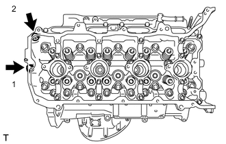
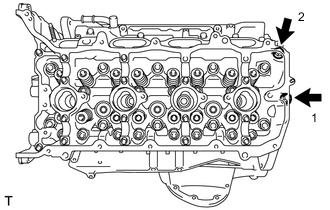
Install the 2 cylinder head set bolts in the order shown in the illustration.
21 N*m 214 kgf*cm 15 ft.*lbf -
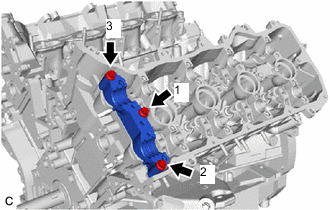
Place the camshaft housing RH on the cylinder head sub-assembly.
-
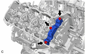
Temporarily tighten the 3 bolts in the order shown in the illustration.
10 N*m 102 kgf*cm 7 ft.*lbf -
Fully tighten the 3 bolts in the order shown in the illustration.
24 N*m 245 kgf*cm 18 ft.*lbf
-
- Click here
INSTALL NO. 2 CYLINDER HEAD GASKET
-
*a Lot No. Engine Front Place the No. 2 cylinder head gasket on the cylinder block sub-assembly with the Lot No. stamp facing upward.
Note:
-
Be sure to place the gasket in the correct orientation.
-
Gently place the cylinder head LH in order not to damage the No. 2 cylinder head gasket with the bottom of the cylinder head LH.
-
-
- Click here
INSTALL CYLINDER HEAD LH
-
Place the cylinder head LH on the cylinder block sub-assembly.
Note:
-
Clean all contact surfaces.
-
Inspect and clean each cylinder head set bolt and bolt hole.
-
Gently place the cylinder head LH in order not to damage the No. 2 cylinder head gasket with the bottom part of the cylinder head LH.
-
-
Apply a light coat of engine oil to the threads and under the heads of the cylinder head set bolts.
Tip:The cylinder head set bolts are tightened in 3 progressive steps.
-
Step 1:
-
Using a 10 mm bi-hexagon wrench, install and uniformly tighten the 10 cylinder head set bolts with the 10 plate washers in several steps in the order shown in the illustration.
36 N*m 367 kgf*cm 27 ft.*lbf
-
-
Step 2:
-
*a Paint Mark Engine Front Mark each cylinder head set bolt head with paint as shown in the illustration.
-
Tighten the cylinder head set bolts another 90° in the order shown in step 1.
-
-
Step 3:
-
Tighten the cylinder head set bolts by an additional 90° in the order shown in step 1.
-
Check that the paint marks are now facing rearward.
-
-
Install the 2 cylinder head set bolts in the order shown in the illustration.
21 N*m 214 kgf*cm 15 ft.*lbf -
Place the camshaft housing LH on the cylinder head LH.
-
Temporarily tighten the 3 bolts in the order shown in the illustration.
10 N*m 102 kgf*cm 7 ft.*lbf -
Fully tighten the 3 bolts in the order shown in the illustration.
24 N*m 245 kgf*cm 18 ft.*lbf
-
- Click here
INSTALL NO. 1 VALVE ROCKER ARM SUB-ASSEMBLY
- Click here
INSTALL CAMSHAFT
- Click here
INSTALL NO. 2 CAMSHAFT
- Click here
INSTALL CAMSHAFT BEARING CAP (for Bank 2)
Note:When rotating the camshafts without the chain sub-assemblies installed, make sure that the valves do not contact the pistons. If contact occurs between the valves and pistons, damage may result.
-
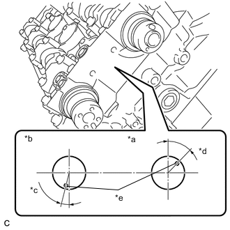
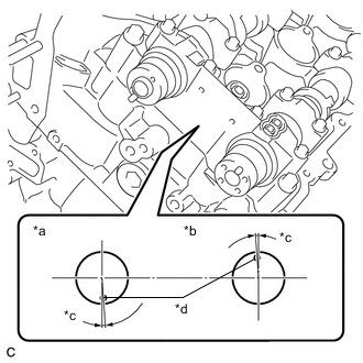
*a Intake Side *b Exhaust Side *c 14° *d 44° *e Knock Pin Make sure that the knock pin of each camshaft is positioned as shown in the illustration.
-
Apply a light coat of engine oil to the camshaft housing RH and camshaft bearing caps.
-
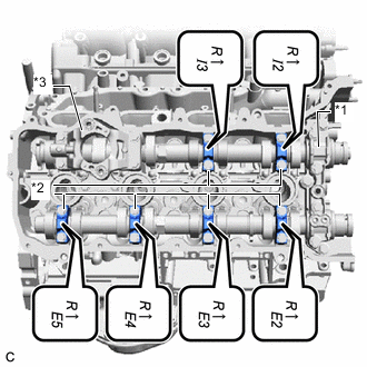
*1 No. 1 Camshaft Bearing Cap *2 No. 3 Camshaft Bearing Cap *3 No. 4 Camshaft Bearing Cap Confirm the marks and numbers on the No. 1 camshaft bearing cap, No. 3 camshaft bearing caps and No. 4 camshaft bearing cap and place them in their proper positions and orientations.
-
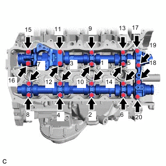
Install the 20 bolts in the order shown in the illustration.
18.5 N*m 189 kgf*cm 14 ft.*lbf
-
- Click here
INSTALL OIL REFLECTOR PLATE RH
- Click here
INSTALL NO. 3 CAMSHAFT SUB-ASSEMBLY
- Click here
INSTALL NO. 4 CAMSHAFT SUB-ASSEMBLY
- Click here
INSTALL CAMSHAFT BEARING CAP (for Bank 1)
Note:When rotating the camshafts without the chain sub-assemblies installed, make sure that the valves do not contact the pistons. If contact occurs between the valves and pistons, damage may result.
-
*a Intake Side *b Exhaust Side *c 4° *d Knock Pin Make sure the knock pin of each camshaft is positioned as shown in the illustration.
-
Apply a light coat of engine oil to the camshaft housing LH and camshaft bearing caps.
-
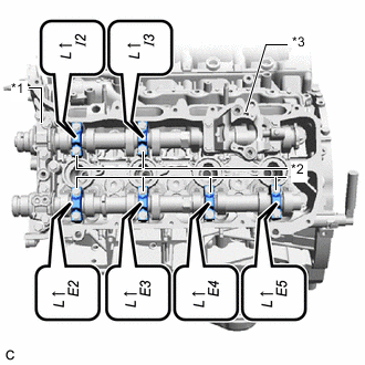
*1 No. 2 Camshaft Bearing Cap *2 No. 3 Camshaft Bearing Cap *3 No. 4 Camshaft Bearing Cap Confirm the marks and numbers on the No. 2 camshaft bearing cap, No. 3 camshaft bearing caps and No. 4 camshaft bearing cap and place them in their proper positions and orientations.
-
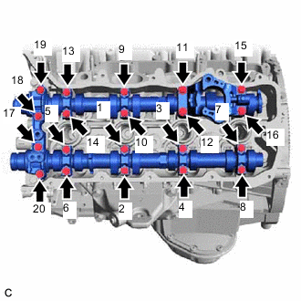
Install the 20 bolts in the order shown in the illustration.
18.5 N*m 189 kgf*cm 14 ft.*lbf
-
- Click here
INSTALL OIL REFLECTOR PLATE LH
- Click here
INSTALL FUEL INJECTOR ASSEMBLY (for Direct Injection)
- Click here
INSTALL EXHAUST MANIFOLD SUB-ASSEMBLY LH (TWC: Front Catalyst)
- Click here
INSTALL EXHAUST MANIFOLD SUB-ASSEMBLY RH (TWC: Front Catalyst)
- Click here
INSTALL ENGINE ASSEMBLY WITH TRANSMISSION