CYLINDER HEAD GASKET REMOVAL
PROCEDURE
-
REMOVE ENGINE ASSEMBLY WITH TRANSMISSION
-
REMOVE EXHAUST MANIFOLD SUB-ASSEMBLY LH (TWC: Front Catalyst)
-
REMOVE EXHAUST MANIFOLD SUB-ASSEMBLY RH (TWC: Front Catalyst)
-
REMOVE FUEL INJECTOR ASSEMBLY
-
REMOVE NO. 3 CAMSHAFT SUB-ASSEMBLY
-
REMOVE NO. 4 CAMSHAFT SUB-ASSEMBLY
-
REMOVE OIL REFLECTOR PLATE RH
-
REMOVE CAMSHAFT BEARING CAP (for Bank 2)
Tech Tips
When rotating the camshafts without the chain sub-assemblies installed, make sure that the valves do not contact the pistons. If contact occurs between the valves and pistons, damage may result.
-
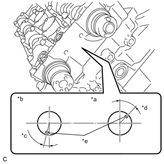
*a Intake Side *b Exhaust Side *c 14° *d 44° *e Knock Pin Make sure that the knock pin of each camshaft is positioned as shown in the illustration.
-
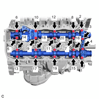
Uniformly loosen and remove the 20 bolts in the order shown in the illustration.
Tech Tips
Uniformly loosen the bolts while keeping the camshaft level.
-
Remove the 8 camshaft bearing caps.
Tech Tips
Arrange the removed parts in such a way that they can be installed to their original locations.
-
-
REMOVE CAMSHAFT
-
REMOVE NO. 2 CAMSHAFT
-
REMOVE NO. 1 VALVE ROCKER ARM SUB-ASSEMBLY
-
REMOVE CYLINDER HEAD LH
-
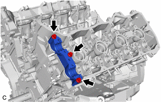
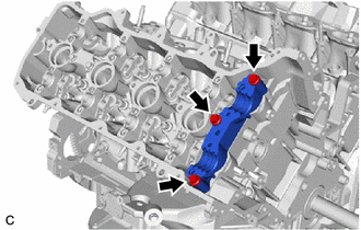
Remove the 3 bolts and camshaft housing LH.
-
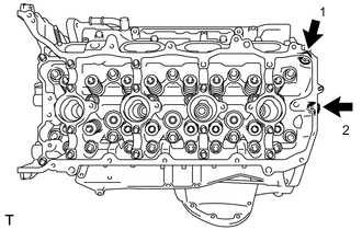
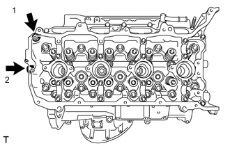
Uniformly loosen and remove the 2 cylinder head set bolts in the order shown in the illustration.
-
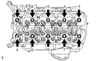
Using a 10 mm bi-hexagon wrench, uniformly loosen the 10 cylinder head set bolts in the order shown in the illustration. Remove the 10 cylinder head set bolts and plate washers.
Note
-
Be careful not to drop the plate washers into the cylinder head LH.
-
Warpage or cracking of the cylinder head LH could result from removing the bolts in an incorrect order.
Tech Tips
Arrange the removed parts in such a way that they can be installed to their original locations.
-
-
Remove the cylinder head LH.
-
-
REMOVE NO. 2 CYLINDER HEAD GASKET
-
Remove the No. 2 cylinder head gasket.
-
-
REMOVE CYLINDER HEAD SUB-ASSEMBLY
-
Remove the 3 bolts and camshaft housing RH.
-
Uniformly loosen and remove the 2 cylinder head set bolts in the order shown in the illustration.
-
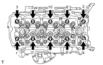
Using a 10 mm bi-hexagon wrench, uniformly loosen the 10 cylinder head set bolts in the order shown in the illustration. Remove the 10 cylinder head set bolts and plate washers.
Note
-
Be careful not to drop the plate washers into the cylinder head sub-assembly.
-
Warpage or cracking of the cylinder head sub-assembly could result from removing the bolts in an incorrect order.
Tech Tips
Arrange the removed parts in such a way that they can be installed to their original locations.
-
-
Remove the cylinder head sub-assembly.
-
-
REMOVE CYLINDER HEAD GASKET
-
Remove the cylinder head gasket.
-