PROCEDURE
- Click here
INSTALL CAMSHAFT
-
Apply a light coat of engine oil to the camshaft journals.
-
Install the camshaft to the cylinder head sub-assembly.
-
- Click here
INSTALL NO. 2 CAMSHAFT
-
Apply a light coat of engine oil to the camshaft journals.
-
Install the No. 2 camshaft to the cylinder head sub-assembly.
-
- Click here
INSTALL CAMSHAFT BEARING CAP (for Bank 2)
Note:When rotating the camshafts without the chain sub-assemblies installed, be careful to ensure that the valves do not contact the pistons. If contact occurs between the valves and pistons, damage may result.
-
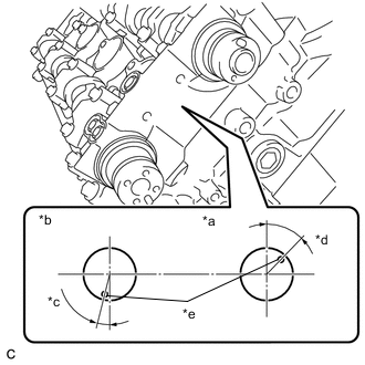
*a Intake Side *b Exhaust Side *c 14° *d 44° *e Knock Pin Make sure that the knock pin of each camshaft is positioned as shown in the illustration.
-
Apply a light coat of engine oil to the camshaft housing RH and camshaft bearing caps.
-
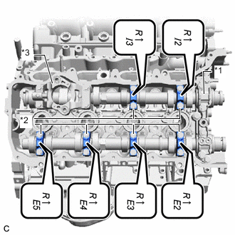
*1 No. 1 Camshaft Bearing Cap *2 No. 3 Camshaft Bearing Cap *3 No. 4 Camshaft Bearing Cap Confirm the marks and numbers on the No. 1 camshaft bearing cap, No. 3 camshaft bearing caps and No. 4 camshaft bearing cap and place them in their proper positions and orientations.
-
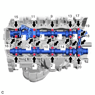
Install the 20 bolts in the order shown in the illustration.
18.5 N*m 189 kgf*cm 14 ft.*lbf
-
- Click here
INSTALL OIL REFLECTOR PLATE RH
- Click here
INSTALL NO. 3 CAMSHAFT SUB-ASSEMBLY
-
Apply a light coat of engine oil to the camshaft journals.
-
Install the No. 3 camshaft sub-assembly to the cylinder head LH.
-
- Click here
INSTALL NO. 4 CAMSHAFT SUB-ASSEMBLY
-
Apply a light coat of engine oil to the camshaft journals.
-
Install the No. 4 camshaft sub-assembly to the cylinder head LH.
-
- Click here
INSTALL CAMSHAFT BEARING CAP (for Bank 1)
Note:When rotating the camshafts without the chain sub-assemblies installed, be careful to ensure that the valves do not contact the pistons. If contact occurs between the valves and pistons, damage may result.
-
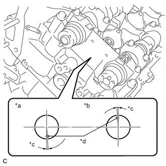
*a Intake Side *b Exhaust Side *c 4° *d Knock Pin Make sure the knock pin of each camshaft is positioned as shown in the illustration.
-
Apply a light coat of engine oil to the camshaft housing LH and camshaft bearing caps.
-
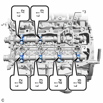
*1 No. 2 Camshaft Bearing Cap *2 No. 3 Camshaft Bearing Cap *3 No. 4 Camshaft Bearing Cap Confirm the marks and numbers on the No. 2 camshaft bearing cap, No. 3 camshaft bearing caps and No. 4 camshaft bearing cap and place them in their proper positions and orientations.
-
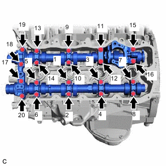
Install the 20 bolts in the order shown in the illustration.
18.5 N*m 189 kgf*cm 14 ft.*lbf
-
- Click here
INSTALL OIL REFLECTOR PLATE LH
- Click here
INSTALL NO. 2 CHAIN TENSIONER ASSEMBLY
- Click here
INSTALL CHAIN SUB-ASSEMBLY (for Bank 2)
- Click here
INSTALL NO. 1 CHAIN VIBRATION DAMPER (for Bank 2)
- Click here
INSTALL CHAIN TENSIONER SLIPPER (for Bank 2)
- Click here
INSTALL NO. 1 CHAIN TENSIONER ASSEMBLY (for Bank 2)
- Click here
INSTALL NO. 3 CHAIN TENSIONER ASSEMBLY
- Click here
INSTALL CHAIN SUB-ASSEMBLY (for Bank 1)
- Click here
INSTALL NO. 1 CHAIN VIBRATION DAMPER (for Bank 1)
- Click here
INSTALL CHAIN TENSIONER SLIPPER (for Bank 1)
- Click here
INSTALL NO. 1 CHAIN TENSIONER ASSEMBLY (for Bank 1)
- Click here
TIGHTEN CAMSHAFT TIMING GEAR ASSEMBLY (for Bank 1)
- Click here
INSTALL CAMSHAFT TIMING GEAR ASSEMBLY (for Bank 2)
- Click here
INSPECT NO. 1 CYLINDER TO TDC / COMPRESSION
- Click here
INSPECT VALVE CLEARANCE
- Click here
ADJUST VALVE CLEARANCE
- Click here
INSTALL TIMING CHAIN COVER ASSEMBLY