PROCEDURE
- Click here
INSPECT ENGINE COOLANT
- Click here
INSPECT ENGINE OIL
- Click here
INSPECT BATTERY
- Click here
CHECK SPARK PLUG
- Click here
INSPECT AIR CLEANER FILTER ELEMENT SUB-ASSEMBLY
-
Remove the air cleaner cap with air cleaner hose.
-
Remove the air cleaner filter element sub-assembly.
-
Visually check that the air cleaner filter element sub-assembly is not excessively damaged or oily.
Tip:
-
If necessary, replace the air cleaner filter element sub-assembly.
-
If there is any dirt or clogs in the air cleaner filter element sub-assembly, clean it with compressed air.
-
If any dirt or clogs remain even after cleaning the air cleaner filter element sub-assembly with compressed air, replace it.
-
-
Install the air cleaner filter element sub-assembly.
-
Install the air cleaner cap with air cleaner hose.
-
- Click here
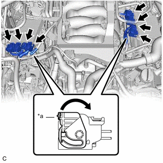
INSPECT V-RIBBED BELT TENSIONER ASSEMBLY
-
Remove the V-ribbed belt.
-
Check that nothing is caught in the V-ribbed belt tensioner assembly by turning it clockwise and counterclockwise.
Tip:If a malfunction exists, replace the V-ribbed belt tensioner assembly.
-
Install the V-ribbed belt.
-
- Click here
INSPECT VALVE CLEARANCE
- Click here
INSPECT IGNITION TIMING
-
Warm up and stop the engine.
Tip:A warmed up engine should have an engine coolant temperature of over 80°C (176°F), an engine oil temperature of 60°C (140°F), and the engine speed should be stabilized.
-
When using the Techstream:
-
Connect the Techstream to the DLC3.
-
Start the engine and run it at idle.
-
Turn the Techstream on.
-
Enter the following menus: Powertrain / Engine / Data List / IGN Advance.
- Powertrain > Engine > Data List
Tester Display IGN Advance -
-
-
-
Standard Ignition Timing 8 to 18° BTDC at idle Note:
-
Check the ignition timing with the cooling fans off.
-
Turn off all electrical systems and the A/C.
-
When checking the ignition timing, the transmission should be in neutral or park.
- Powertrain > Engine > Data List
-
Check that the ignition timing advances immediately when the engine speed is increased.
-
Enter the following menus: Powertrain / Engine / Active Test / Connect the TC and TE1 / ON.
- Powertrain > Engine > Active Test
Active Test Display Connect the TC and TE1 Data List Display IGN Advance -
-
-
-
- Powertrain > Engine > Active Test
-
Monitor IGN Advance.
-
Perform the Active Test.
Standard Ignition Timing 8 to 12° BTDC at idle Note:
-
Check the ignition timing with the cooling fan off.
-
Turn off all electrical systems and the A/C.
-
When checking the ignition timing, the transmission should be in neutral or park.
-
-
-
When not using the Techstream:
-
Remove the V-bank cover sub-assembly.
-
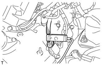
Connect the clip of a timing light to the ignition coil wire for the No. 1 cylinder.
Note:Use a timing light that detects primary signals.
-
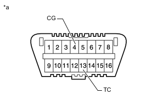
*a DLC3 Using SST, connect terminals 13 (TC) and 4 (CG) of the DLC3.
09843-18040 Note:
-
Confirm the terminal numbers before connecting them. Connecting the wrong terminals may damage to electrical components.
-
Check the ignition timing with the cooling fans off.
-
Turn off all the electrical systems and the A/C.
-
When checking the ignition timing, the transmission should be in neutral or park.
-
-
Connect the clip of a timing light to the ignition coil wire for the No. 1 cylinder.
Note:Use a timing light that detects primary signals.
-
Start the engine and run it at idle.
-
Check the ignition timing at idle.
Standard Ignition Timing 8 to 12° BTDC at idle Note:When checking the ignition timing, the transmission should be in neutral or park.
Tip:Run the engine at 1000 to 1300 rpm for 5 seconds, and then check that the engine rpm returns to engine idle speed.
-
Disconnect terminals 13 (TC) and 4 (CG) of the DLC3.
-
Check the ignition timing at idle.
Standard Ignition Timing 8 to 18° BTDC at idle -
Check that the ignition timing advances immediately when the engine idle speed is increased.
-
Disconnect the clip of the timing light from the ignition coil wire for the No. 1 cylinder.
-
Install the V-bank cover sub-assembly.
-
-
- Click here
INSPECT ENGINE IDLE SPEED
-
Warm up and stop the engine.
Tip:A warmed up engine should have an engine coolant temperature of over 80°C (176°F), an engine oil temperature of 60°C (140°F), and the engine idle speed should be stabilized.
-
When using the Techstream:
-
Connect the Techstream to the DLC3.
-
Start the engine and run it at idle.
-
Turn the Techstream on.
-
Enter the following menus: Powertrain / Engine / Data List / Engine Speed.
- Powertrain > Engine > Data List
Tester Display Engine Speed -
-
-
-
- Powertrain > Engine > Data List
-
Inspect the engine idle speed.
Standard Idle Speed 700 to 800 rpm Note:
-
Check the idle speed with the cooling fans off.
-
Turn off all the electrical systems and the A/C.
-
When checking the engine idle speed, the transmission should be in neutral or park.
Tip:Refer to the Techstream operator's manual for further details.
If the idle speed is not as specified, check the air intake system.
-
-
-
When not using the Techstream:
-
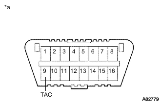
*a DLC3 Using SST, connect a tachometer probe to terminal 9 (TAC) of the DLC3.
09843-18030 Note:Confirm the terminal numbers before connecting them. Connecting the wrong terminals may damage the electrical components.
-
Start the engine and run it at idle.
-
Inspect the engine idle speed.
Standard Idle Speed 700 to 800 rpm Note:
-
Check the engine idle speed with the cooling fans off.
-
Turn off all the electrical systems and the A/C.
-
When checking the engine idle speed, the transmission should be in neutral or park.
Tip:If the idle speed is not as specified, check the air intake system.
-
-
Turn the engine switch off.
-
Disconnect the tachometer probe from terminal 9 (TAC) of the DLC3.
-
-
- Click here
INSPECT COMPRESSION
-
Warm up and stop the engine.
Tip:A warmed up engine should have an engine coolant temperature of over 80°C (176°F), an engine oil temperature of 60°C (140°F), and the engine idle speed should be stabilized.
-
Disconnect the cable from the negative (-) battery terminal.
-
Remove the air cleaner cap with air cleaner hose.
-
Remove the battery.
-
Remove the 8 spark plugs.
-
Disconnect the throttle with motor body connector.
-
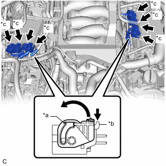
*a Lock Lever *b Lock *c Connector (with Lock) Disconnect the 6 injector driver connectors from the 2 injector drivers.
-
Disconnect the 2 injector driver connectors.
-
Insert a compression gauge into the spark plug hole.
-
Install the battery.
-
Connect the cable to the negative (-) battery terminal.
-
Fully open the throttle valve.
-
Depress and hold the brake pedal, and turn the engine switch on (IG). Then check the compression pressure.
Standard Compression Pressure 1400 kPa (14.3 kgf/cm2, 203 psi) Minimum Compression Pressure 1000 kPa (10.2 kgf/cm2, 145 psi) Pressure Difference between Each Cylinder 100 kPa (1.0 kgf/cm2, 15 psi) or less Note:
-
Always use a fully charged battery to obtain an engine speed of 250 rpm or more.
-
Inspect all cylinders in the same way.
-
Measure the compression pressure as quickly as possible.
-
If the cylinder compression pressure is low, pour a small amount of engine oil into the cylinder through the spark plug hole, then inspect it again.
Tip:
-
If adding oil increases the compression pressure, the piston rings and/or cylinder bore may be worn or damaged.
-
If the compression pressure stays low, a valve may be stuck or seated improperly, or there may be leaks in the cylinder head gasket.
-
-
-
Disconnect the cable to the negative (-) battery terminal.
-
Remove the battery.
-
Install the 8 spark plugs.
-
Install the battery.
-
Install the air cleaner cap with air cleaner hose.
-
*a Lock Lever Connect the 2 injector driver connectors.
-
Connect the 6 injector driver connectors to the 2 injector drivers.
-
Connect the throttle with motor body connector.
-
Connect the cable to the negative (-) battery terminal.
-
Clear the DTCs.
Note:After the inspection, clear the DTCs, check for DTCs again and make sure the normal system code is output.
-
- Click here
INSPECT CO/HC
Tip:This check determines whether the idle CO/HC complies with regulations.
-
Start the engine.
-
Keep the engine speed at 2500 rpm for approximately 180 seconds.
-
Insert a CO/HC meter testing probe at least 40 cm (1.31 ft.) into the tailpipe during idle.
-
Check the CO/HC concentration during idle and when the engine is running at 2500 rpm.
Tip:When performing the 2 mode (with the engine idling/running at 2500 rpm) test, the measurement procedures are determined by applicable local regulations.
If the CO/HC concentration does not comply with the regulations, perform troubleshooting in the following order.
-
Check the A/F sensor and heated oxygen sensor operation.
-
Check for DTCs.
-
See the following table for possible causes, then inspect the applicable parts and repair them if necessary.
CO HC Problem Cause Normal High Rough idle
-
Faulty ignition:
-
-
Incorrect valve timing
-
Fouled, shorted or improperly gapped spark plugs
-
-
Leaks in intake or exhaust valves
-
Leaks in cylinders
Low High Rough idle
(Fluctuating HC reading)
-
Vacuum leaks:
-
-
PCV hoses
-
Intake manifold
-
Throttle with motor body assembly
-
-
Lean mixture causing misfire
High High Rough idle
(Black smoke from exhaust)
-
Restricted air cleaner filter element sub-assembly
-
Plugged PCV valve
-
Faulty SFI system:
-
-
Incorrect pressure
-
ECT sensor
-
ECM
-
Fuel injector assemblies
-
Throttle position sensor (built into throttle with motor body assembly)
-
MAF sensor
-
-
-
-