PROCEDURE
- Click here
INSPECT INJECTOR RELAY (INJ NO. 1)
-
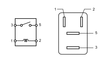
Measure the resistance according to the value(s) in the table below.
Standard Resistance Tester Connection Condition Specified Condition 3 - 5 Battery voltage not applied between terminals 1 and 2 10 kΩ or higher Battery voltage applied between terminals 1 and 2 Below 1 Ω If the result is not as specified, replace the injector relay (INJ NO. 1).
-
- Click here
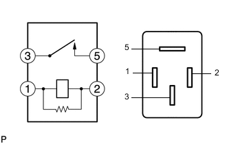
INSPECT INJECTOR RELAY (INJ NO. 2)
-
Measure the resistance according to the value(s) in the table below.
Standard Resistance Tester Connection Condition Specified Condition 3 - 5 Battery voltage not applied between terminals 1 and 2 10 kΩ or higher Battery voltage applied between terminals 1 and 2 Below 1 Ω If the result is not as specified, replace the injector relay (INJ NO. 2).
-
- Click here
INSPECT EFI CIRCUIT OPENING RELAY ASSEMBLY (C/OPN)
-
Measure the resistance according to the value(s) in the table below.
Standard Resistance Tester Connection Condition Specified Condition 3 - 5 Battery voltage not applied between terminals 1 and 2 10 kΩ or higher Battery voltage applied between terminals 1 and 2 Below 1 Ω If the result is not as specified, replace the EFI circuit opening relay assembly (C/OPN).
-
- Click here
INSPECT EFI 2 RELAY (EFI MAIN NO. 2)
-
Measure the resistance according to the value(s) in the table below.
Standard Resistance Tester Connection Condition Specified Condition 3 - 5 Battery voltage not applied between terminals 1 and 2 10 kΩ or higher Battery voltage applied between terminals 1 and 2 Below 1 Ω If the result is not as specified, replace the EFI 2 relay (EFI MAIN NO. 2).
-
- Click here
INSPECT VVT RELAY (VVT RH)
-
Measure the resistance according to the value(s) in the table below.
Standard Resistance Tester Connection Condition Specified Condition 3 - 5 Battery voltage not applied between terminals 1 and 2 10 kΩ or higher Battery voltage applied between terminals 1 and 2 Below 1 Ω If the result is not as specified, replace the VVT relay (VVT RH).
-
- Click here
INSPECT VVT RELAY (VVT LH)
-
Measure the resistance according to the value(s) in the table below.
Standard Resistance Tester Connection Condition Specified Condition 3 - 5 Battery voltage not applied between terminals 1 and 2 10 kΩ or higher Battery voltage applied between terminals 1 and 2 Below 1 Ω If the result is not as specified, replace the VVT relay (VVT LH).
-