VALVE CLEARANCE ADJUSTMENT
PROCEDURE
-
REMOVE FUEL PUMP WITH SEAL SUB-ASSEMBLY (for Bank 1)
-
REMOVE FUEL PUMP WITH SEAL SUB-ASSEMBLY (for Bank 2)
-
DISENGAGE ENGINE WIRE
-
REMOVE IGNITION COIL ASSEMBLY
-
REMOVE CYLINDER HEAD COVER SUB-ASSEMBLY
-
REMOVE CYLINDER HEAD COVER SUB-ASSEMBLY LH
-
REMOVE OIL REFLECTOR PLATE LH
-
REMOVE OIL REFLECTOR PLATE RH
-
SET NO. 1 CYLINDER TO TDC/COMPRESSION
-
INSPECT VALVE CLEARANCE
-
Using a feeler gauge, measure the clearance between the indicated No. 1 valve rocker arm sub-assemblies and camshafts.
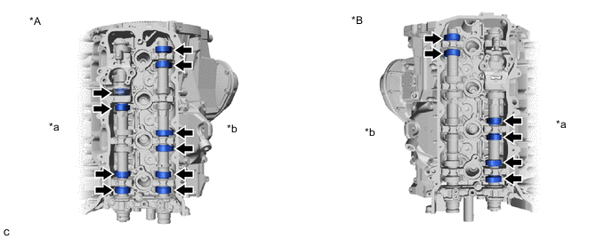
*A for Bank 1 *B for Bank 2 *a Intake Side *b Exhaust Side Standard Valve Clearance (Cold) Intake 0.12 to 0.18 mm (0.00472 to 0.00709 in.) Exhaust 0.22 to 0.28 mm (0.00866 to 0.0110 in.) Tech Tips
-
On this engine, valve clearance is measured between the No. 1 valve rocker arm sub-assemblies and the camshaft lobes. The shims used to adjust the valve clearance are located on the top of the valve stems.
-
The valve clearance shown in the Standard Valve Clearance table is the clearance as measured between the cam lobe and No. 1 valve rocker arm sub-assembly.
-
Record any out-of-specification valve clearance measurements. They will be used later to determine the required replacement valve adjusting shim.
-
-
Turn the crankshaft 1 revolution (360°).
-
Using a feeler gauge, measure the clearance between the indicated No. 1 valve rocker arm sub-assemblies and camshafts.
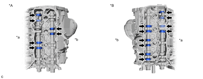
*A for Bank 1 *B for Bank 2 *a Intake Side *b Exhaust Side Standard Valve Clearance (Cold) Intake 0.12 to 0.18 mm (0.00472 to 0.00709 in.) Exhaust 0.22 to 0.28 mm (0.00866 to 0.0110 in.) Tech Tips
-
On this engine, valve clearance is measured between the No. 1 valve rocker arm sub-assemblies and the camshaft lobes. The shims used to adjust the valve clearance are located on the top of the valve stems.
-
The valve clearance shown in the Standard Valve Clearance table is the clearance as measured between the cam lobe and No. 1 valve rocker arm sub-assembly.
-
Record any out-of-specification valve clearance measurements. They will be used later to determine the required replacement valve adjusting shim.
-
-
-
ADJUST VALVE CLEARANCE
-
Remove timing chain cover assembly.
-
Remove the camshafts.
-
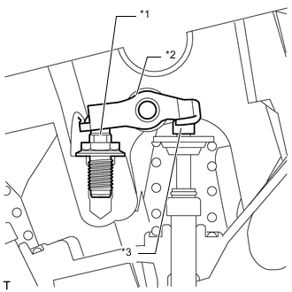
*1 Cylinder Head Valve Rocker Arm Pivot *2 No. 1 Valve Rocker Arm Sub-assembly *3 Valve Adjusting Shim Raise the No. 1 valve rocker arm sub-assembly above the valve adjusting shim being replaced, and remove the valve adjusting shim.
Note
-
Be careful not to drop the valve adjusting shim into the cylinder head LH and cylinder head sub-assembly.
Tech Tips
Arrange the removed parts in such a way that they can be installed to their original locations.
-
-
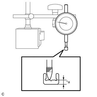
*a Groove Using a dial gauge, measure the thickness of the existing valve adjusting shim after removing it.
Tech Tips
Do not measure at the valve adjusting shim center groove.
-
Determine the replacement valve adjusting shim thickness according to the formula or following charts.
T2 Thickness of replacement shim T1 Thickness of existing shim A Measured valve clearance Valve Clearance Intake T2 = T1 + (A - 0.15 mm (0.0059055 in.)) x 1.7 Exhaust T2 = T1 + (A - 0.25 mm (0.00984 in.)) x 1.7 These examples are provided only as calculation examples, based on the clearance adjustment of an intake valve. If non-metric units are being used, substitute those measurements for the following values.
Step 1 - Determining the amount of excess clearance
The specified clearance (0.15) is subtracted from the measured value (0.40), and the result is then multiplied by the rocker ratio compensation value (1.8).
(Measured value - Specified clearance) x Compensation value = Amount of excess clearance
(0.40 - 0.15) x 1.8 = 0.450
Step 2 - Using the existing valve adjusting shim to determine the required thickness of the replacement valve adjusting shim
The amount of excess clearance (0.450) is added to the thickness of the existing valve adjusting shim (2.300). The resulting value is the thickness of a replacement valve adjusting shim.
Excess clearance + Thickness of existing shim = Thickness of replacement shim
0.450 + 2.300 = 2.750
Step 3 - Select the valve adjusting shim closest to the thickness of the required replacement shim
Compare the thickness of the available replacement valve adjusting shims to the required replacement shim and choose the shim that is the closest match.
Closest replacement valve adjusting shim = 2.750 (Select a new No. 74 shim.)
Tech Tips
-
Select a replacement shim with a thickness as close to the calculated value as possible.
-
Valve adjusting shims are available in 41 sizes in increments of 0.020 mm (0.000787 in.), from 2.000 mm (0.0787 in.) to 2.800 mm (0.11024 in.).
-
To select a replacement valve adjusting shim, refer to the following Valve Adjusting Shim Selection Chart and New Lifter Thickness tables.
Figure 1. Valve Adjusting Shim Selection Chart (Intake)
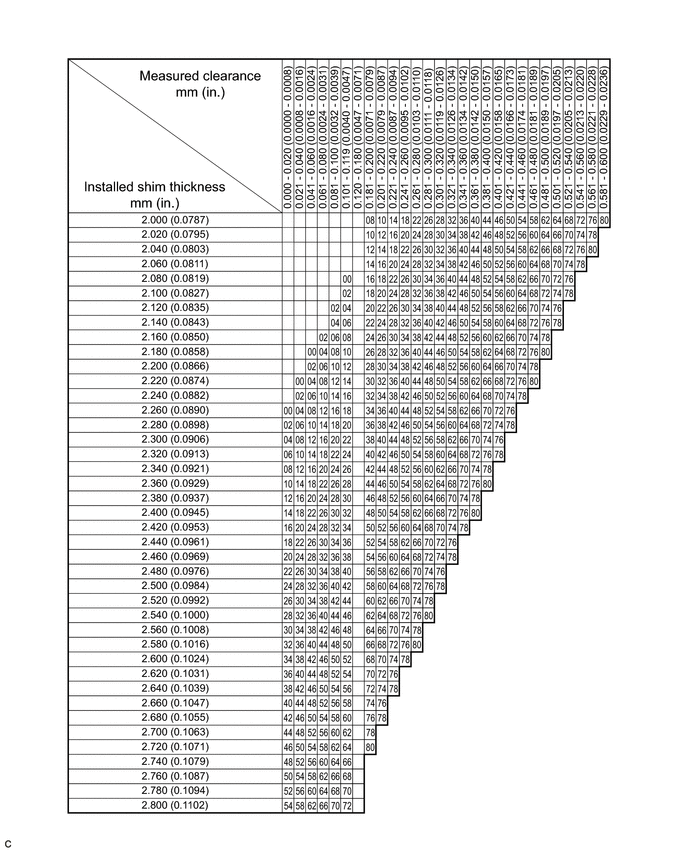
Intake Valve Clearance (Cold) 0.12 to 0.18 mm (0.00472 to 0.00709 in.) EXAMPLE:
If the existing shim (installed shim) is 2.300 mm (0.0906 in.), and the measured clearance is 0.39 mm (0.0154 in.), then a new 2.740 mm (0.1079 in.) No. 74 shim should be used as a replacement for the existing shim.
New Lifter Thickness mm (in.) Lifter No. Thickness Lifter No. Thickness Lifter No. Thickness 00 2.000 (0.0787) 28 2.280 (0.0898) 56 2.560 (0.1008) 02 2.020 (0.0795) 30 2.300 (0.0906) 58 2.580 (0.1016) 04 2.040 (0.0803) 32 2.320 (0.0913) 60 2.600 (0.1024) 06 2.060 (0.0811) 34 2.340 (0.0921) 62 2.620 (0.1031) 08 2.080 (0.0819) 36 2.360 (0.0929) 64 2.640 (0.1039) 10 2.100 (0.0827) 38 2.380 (0.0937) 66 2.660 (0.1047) 12 2.120 (0.0835) 40 2.400 (0.0945) 68 2.680 (0.1055) 14 2.140 (0.0843) 42 2.420 (0.0953) 70 2.700 (0.1063) 16 2.160 (0.0850) 44 2.440 (0.0961) 72 2.720 (0.1071) 18 2.180 (0.0858) 46 2.460 (0.0969) 74 2.740 (0.1079) 20 2.200 (0.0866) 48 2.480 (0.0976) 76 2.760 (0.1087) 22 2.220 (0.0874) 50 2.500 (0.0984) 78 2.780 (0.1094) 24 2.240 (0.0882) 52 2.520 (0.0992) 80 2.800 (0.1102) 26 2.260 (0.0890) 54 2.540 (0.1000) - - Figure 2. Valve Adjusting Shim Selection Chart (Exhaust)
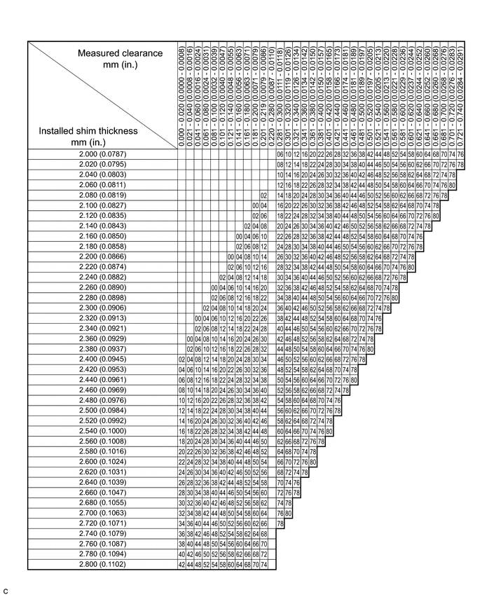
Exhaust Valve Clearance (Cold) 0.22 to 0.28 mm (0.00866 to 0.0110 in.) EXAMPLE:
If the existing shim (installed shim) is 2.300 mm (0.0906 in.), and the measured clearance is 0.39 mm (0.0154 in.), then a new 2.520 mm(0.0992 in.) No. 52 shim should be used as a replacement for the existing shim.
New Lifter Thickness mm (in.) Lifter No. Thickness Lifter No. Thickness Lifter No. Thickness 00 2.000 (0.0787) 28 2.280 (0.0898) 56 2.560 (0.1008) 02 2.020 (0.0795) 30 2.300 (0.0906) 58 2.580 (0.1016) 04 2.040 (0.0803) 32 2.320 (0.0913) 60 2.600 (0.1024) 06 2.060 (0.0811) 34 2.340 (0.0921) 62 2.620 (0.1031) 08 2.080 (0.0819) 36 2.360 (0.0929) 64 2.640 (0.1039) 10 2.100 (0.0827) 38 2.380 (0.0937) 66 2.660 (0.1047) 12 2.120 (0.0835) 40 2.400 (0.0945) 68 2.680 (0.1055) 14 2.140 (0.0843) 42 2.420 (0.0953) 70 2.700 (0.1063) 16 2.160 (0.0850) 44 2.440 (0.0961) 72 2.720 (0.1071) 18 2.180 (0.0858) 46 2.460 (0.0969) 74 2.740 (0.1079) 20 2.200 (0.0866) 48 2.480 (0.0976) 76 2.760 (0.1087) 22 2.220 (0.0874) 50 2.500 (0.0984) 78 2.780 (0.1094) 24 2.240 (0.0882) 52 2.520 (0.0992) 80 2.800 (0.1102) 26 2.260 (0.0890) 54 2.540 (0.1000) - - -
-
Install the camshafts.
-
Inspect the valve clearance again.
Note
Be sure to inspect the valve clearance with the chain sub-assemblies installed. If a camshaft is rotated without the chain sub-assembly installed, contact between the valves and pistons may occur.
Tech Tips
If the valve clearance is not as specified, readjust the valve clearance.
-
Install the timing chain cover assembly.
-
-
INSTALL OIL REFLECTOR PLATE LH
-
INSTALL OIL REFLECTOR PLATE RH
-
INSTALL CYLINDER HEAD COVER SUB-ASSEMBLY
-
INSTALL CYLINDER HEAD COVER SUB-ASSEMBLY LH
-
INSTALL IGNITION COIL ASSEMBLY
-
ENGAGE ENGINE WIRE
-
INSTALL FUEL PUMP WITH SEAL SUB-ASSEMBLY (for Bank 1)
-
INSTALL FUEL PUMP WITH SEAL SUB-ASSEMBLY (for Bank 2)