CAUTION / NOTICE / HINT
After turning the engine switch off, waiting time may be required before disconnecting the cable from the negative (-) battery terminal. Therefore, make sure to read the disconnecting the cable from the negative (-) battery terminal notices before proceeding with work.
PROCEDURE
- Click here
DISCONNECT CABLE FROM NEGATIVE BATTERY TERMINAL
Note:When disconnecting the cable, some systems need to be initialized after the cable is reconnected.
- Click here
REMOVE V-BANK COVER SUB-ASSEMBLY
- Click here
REMOVE POWER STEERING ECU ASSEMBLY
-
for LHD:
-
for RHD:
-
- Click here
REMOVE BATTERY TRAY (for LHD)
-
Remove the 2 bolts and battery tray.
-
- Click here
REMOVE BATTERY TRAY (for RHD)
-
Remove the 2 bolts and battery tray.
-
- Click here
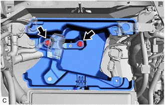
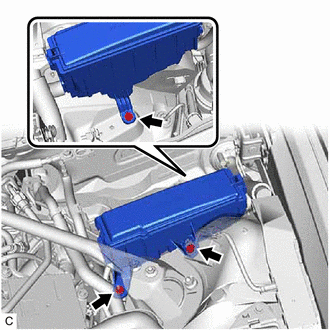
SEPARATE NO. 1 ENGINE ROOM RELAY BLOCK AND NO. 1 JUNCTION BLOCK ASSEMBLY (for LHD)
-
Remove the 2 bolts and nut and separate the No. 1 engine room relay block and No. 1 junction block assembly.
-
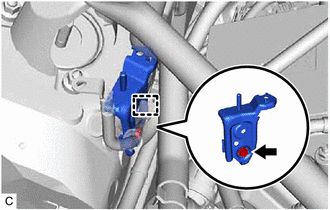
Disengage the wire harness clamp.
-
Remove the bolt and wire harness clamp bracket.
-
- Click here
SEPARATE NO. 1 ENGINE ROOM RELAY BLOCK AND NO. 1 JUNCTION BLOCK ASSEMBLY (for RHD)
-
Remove the 2 bolts and nut and separate the No. 1 engine room relay block and No. 1 junction block assembly.
-
Disengage the wire harness clamp.
-
Remove the bolt and wire harness clamp bracket.
-
- Click here
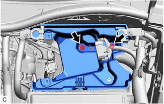
SEPARATE NO. 3 ENGINE ROOM RELAY BLOCK ASSEMBLY (for LHD)
-
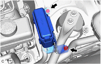
Remove the bolt and nut and separate the No. 3 engine room relay block assembly.
-
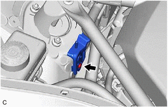
Remove the bolt and wire harness clamp bracket.
-
- Click here
SEPARATE NO. 3 ENGINE ROOM RELAY BLOCK ASSEMBLY (for RHD)
-
Remove the bolt and nut and separate the No. 3 engine room relay block assembly.
-
Remove the bolt and wire harness clamp bracket.
-
- Click here
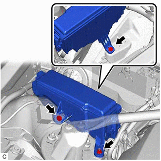
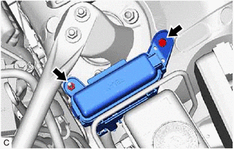
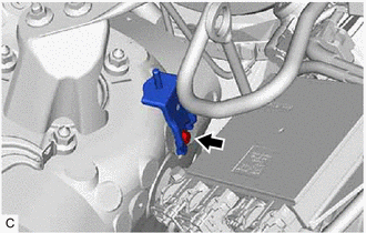
REMOVE NO. 2 VACUUM TRANSMITTING HOSE ASSEMBLY (w/ Differential Pressure Sensor)
-
Disengage the clamp.
-
Slide the 2 clips and remove the No. 2 vacuum transmitting hose assembly from the differential pressure sensor and No. 2 pipe.
-
- Click here
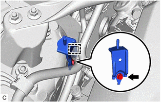
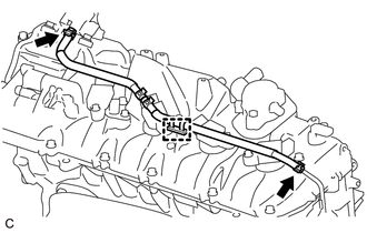
REMOVE NO. 1 VACUUM TRANSMITTING HOSE ASSEMBLY (w/ Differential Pressure Sensor)
-
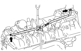
Disengage the clamp.
-
Slide the 2 clips and remove the No. 1 vacuum transmitting hose assembly from the differential pressure sensor and No. 1 pipe.
-
- Click here
REMOVE IGNITION COIL ASSEMBLY
-
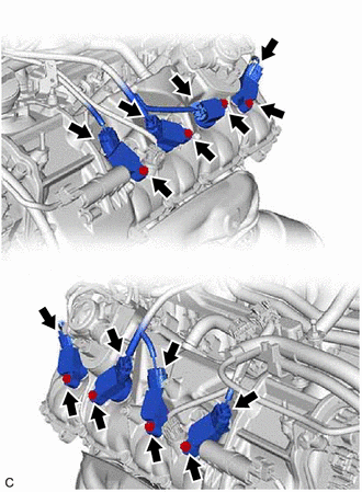
Disconnect the 8 ignition coil assembly connectors.
-
Remove the 8 bolts and 8 ignition coil assemblies from the cylinder head cover sub-assembly and cylinder head cover sub-assembly LH.
Note:If an ignition coil assembly has been struck or dropped, replace it.
Tip:Arrange the removed parts in the correct order.
-
-
Click here
REMOVE SPARK PLUG
-
Remove the 8 spark plugs from the cylinder head sub-assembly and cylinder head LH.
Note:If a spark plug has been struck or dropped, replace it.
Tip:Arrange the removed parts in the correct order.
-