PROCEDURE
- Click here
INSTALL VVT SENSOR (for Intake Side of Bank 1)
-
Apply a light coat of engine oil to the O-ring of the VVT sensor.
Note:If reusing the VVT sensor, be sure to inspect the O-ring.
-
Install the VVT sensor to the cylinder head cover sub-assembly LH with the bolt.
10 N*m 102 kgf*cm 7 ft.*lbf Note:
-
If the VVT sensor has been struck or dropped, replace it.
-
Make sure that the O-ring is not cracked or does not move out of place during installation.
-
-
Connect the VVT sensor connector.
-
- Click here
INSTALL NO. 3 FUEL PIPE SUB-ASSEMBLY
- Click here
INSTALL VVT SENSOR (for Intake Side of Bank 2)
-
Apply a light coat of engine oil to the O-ring of the VVT sensor.
Note:If reusing the VVT sensor, be sure to inspect the O-ring.
-
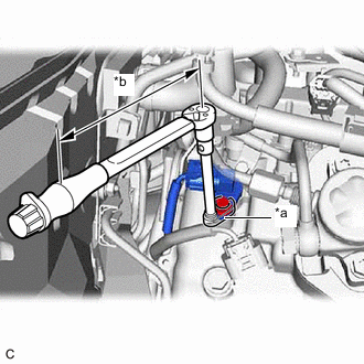
*a 10 mm Union Nut Wrench *b Torque Wrench Fulcrum Length Using a 10 mm union nut wrench, install the VVT sensor to the cylinder head cover sub-assembly with the bolt.
Specified tightening torque 10 N*m 102 kgf*cm 7 ft.*lbf Note:
-
If the VVT sensor has been struck or dropped, replace it.
-
Make sure that the O-ring is not cracked or does not move out of place during installation.
Tip:
-
Calculate the torque wrench reading when changing the fulcrum length of the torque wrench.
-
When using a 10 mm union nut wrench (fulcrum length of 22 mm (0.866 in.)) + torque wrench (fulcrum length of 155 mm (6.1 in.)):
9.0 N*m (92 kgf*cm, 80 in.*lbf)
-
-
Connect the VVT sensor connector.
-
- Click here
INSTALL BATTERY (for LHD)
- Click here
INSTALL VVT SENSOR (for Exhaust Side of Bank 2)
-
Apply a light coat of engine oil to the O-ring of the VVT sensor.
Note:If reusing the VVT sensor, be sure to inspect the O-ring.
-
Install the VVT sensor to the cylinder head cover sub-assembly with the bolt.
10 N*m 102 kgf*cm 7 ft.*lbf Note:
-
If the VVT sensor has been struck or dropped, replace it.
-
Make sure that the O-ring is not cracked or does not move out of place during installation.
-
-
Connect the VVT sensor connector.
-
- Click here
INSTALL VVT SENSOR (for Exhaust Side of Bank 1)
-
Apply a light coat of engine oil to the O-ring of the VVT sensor.
Note:If reusing the VVT sensor, be sure to inspect the O-ring.
-
Install the VVT sensor to the cylinder head cover sub-assembly LH with the bolt.
10 N*m 102 kgf*cm 7 ft.*lbf Note:
-
If the VVT sensor has been struck or dropped, replace it.
-
Make sure that the O-ring is not cracked or does not move out of place during installation.
-
-
Connect the VVT sensor connector.
-
- Click here
INSTALL CAMSHAFT POSITION SENSOR
-
Apply a light coat of engine oil to the O-ring of the camshaft position sensor.
Note:If reusing the camshaft position sensor, be sure to inspect the O-ring.
-
Install the camshaft position sensor to the cylinder head cover sub-assembly with the bolt.
10 N*m 102 kgf*cm 7 ft.*lbf Note:
-
If the camshaft position sensor has been struck or dropped, replace it.
-
Make sure that the O-ring is not cracked or does not move out of place during installation.
-
-
Connect the camshaft position sensor connector.
-
- Click here
INSPECT FOR ENGINE OIL LEAK
- Click here
INSTALL V-BANK COVER SUB-ASSEMBLY
- Click here
CONNECT CABLE TO NEGATIVE BATTERY TERMINAL
Note:When disconnecting the cable, some systems need to be initialized after the cable is reconnected.