CAMSHAFT TIMING CONTROL MOTOR INSTALLATION
PROCEDURE
-
INSTALL CAMSHAFT TIMING CONTROL MOTOR WITH EDU ASSEMBLY RH
-
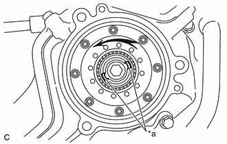
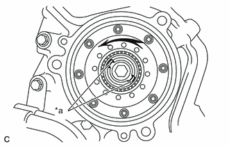
*a Index Slot Turn the camshaft timing gear assembly intermediate shaft index slot counterclockwise by hand, and set it to the maximum retard angle position.
Tech Tips
-
If a camshaft lobe is opening a valve, the intermediate shaft will be difficult to turn.
-
When the intermediate shaft index slot cannot be turned any farther it is set to the maximum retard angle.
-
-
Install a new O-ring to the timing chain or belt cover sub-assembly.
-
Align the joint of the camshaft timing control motor with EDU assembly RH and camshaft timing gear assembly intermediate shaft index slot.
-
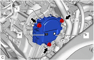
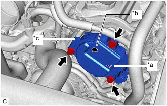
*a "R" Mark *b Arrow *c Knock Pin Install the camshaft timing control motor with EDU assembly RH to the timing chain or belt cover sub-assembly with the 3 bolts.
- Torque:
- 21 N*m { 214 kgf*cm, 15 ft.*lbf }
Note
-
Check that an "R" mark is printed on the label of the camshaft timing control motor with EDU assembly RH.
-
Make sure the contact surface of the camshaft timing control motor with EDU assembly RH (the surface that contacts the timing chain or belt cover sub-assembly) is free of foreign matter.
-
When installing the camshaft timing control motor with EDU assembly RH, do not use excessive force.
-
Install the camshaft timing control motor with EDU assembly RH with the arrow facing upward, as shown in the illustration.
-
Align the camshaft timing control motor with EDU assembly RH pin hole with the timing chain or belt cover sub-assembly knock pin when installing the camshaft timing control motor with EDU assembly RH.
-
If the camshaft timing control motor with EDU assembly RH has been struck or dropped, replace it.
-
Do not disassemble the camshaft timing control motor with EDU assembly RH. If disassembled, replace it.
-
-
ENGAGE ENGINE WIRE
-
Connect the 13 connectors.
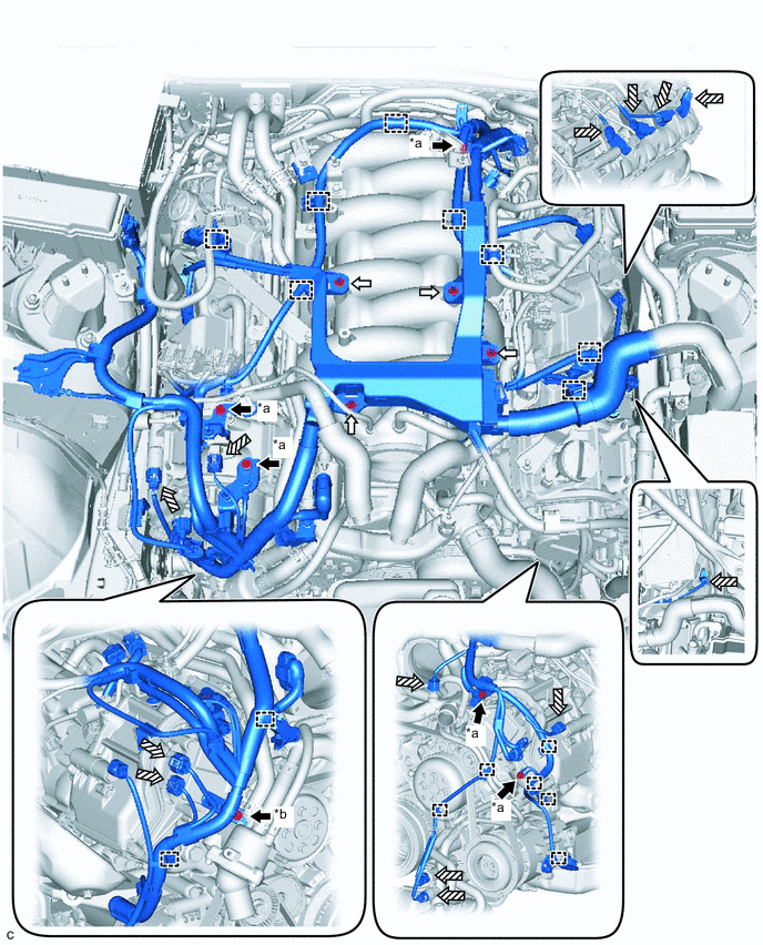
*a Bolt (A) *b Bolt (B) 
Bolt 
Nut 
Connector - - -
Engage the 16 clamps.
-
Install the 6 bolts and 4 nuts.
- Torque:
- Bolt (A) and nut
- 10 N*m { 102 kgf*cm, 7 ft.*lbf }
- Bolt (B)
- 12 N*m { 122 kgf*cm, 9 ft.*lbf }
-
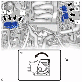
*a Lock Lever *b Connector (with Lock) Connect the 2 injector driver connectors.
-
Connect the 6 connectors (with lock) to the 2 injector drivers and move the lock lever to engage the lock of each connector (with lock) as shown in the illustration.
Note
Securely connect the connectors (with lock) to the injector driver and engage the lock.
-
Engage the wire harness to the engine room ECU box.
-
-
INSTALL ENGINE ROOM ECU COVER
-
INSTALL COOL AIR INTAKE DUCT SEAL
-
INSTALL AIR CLEANER CAP WITH AIR CLEANER HOSE
-
CONNECT VENTILATION HOSE
-
INSTALL CAMSHAFT TIMING CONTROL MOTOR WITH EDU ASSEMBLY LH
-
*a Index Slot Turn the camshaft timing gear assembly intermediate shaft index slot counterclockwise by hand, and set it to the maximum retard angle position.
Tech Tips
-
If a camshaft lobe is opening a valve, the intermediate shaft will be difficult to turn.
-
When the intermediate shaft index slot cannot be turned any farther it is set to the maximum retard angle.
-
-
Install a new O-ring to the timing chain or belt cover sub-assembly.
-
Align the joint of the camshaft timing control motor with EDU assembly LH and camshaft timing gear assembly intermediate shaft index slot.
-
*a "L" Mark *b Arrow *c Knock Pin Install the camshaft timing control motor with EDU assembly LH to the timing chain or belt cover sub-assembly with the 3 bolts.
- Torque:
- 21 N*m { 214 kgf*cm, 15 ft.*lbf }
Note
-
Check that an "L" mark is printed on the label of the camshaft timing control motor with EDU assembly LH.
-
Make sure the contact surface of the camshaft timing control motor with EDU assembly LH (the surface that contacts the timing chain or belt cover sub-assembly) is free of foreign matter.
-
When installing the camshaft timing control motor with EDU assembly LH, do not use excessive force.
-
Install the camshaft timing control motor with EDU assembly LH with the arrow facing upward, as shown in the illustration.
-
Align the camshaft timing control motor with EDU assembly LH pin hole with the timing chain or belt cover sub-assembly knock pin when installing the camshaft timing control motor with EDU assembly LH.
-
If the camshaft timing control motor with EDU assembly LH has been struck or dropped, replace it.
-
Do not disassemble the camshaft timing control motor with EDU assembly LH. If disassembled, replace it.
-
Connect the 2 camshaft timing control motor with EDU assembly LH connectors and engage the clamp.
-
Engage the clamp.
-
-
INSTALL V-BANK COVER SUB-ASSEMBLY
-
CONNECT CABLE TO NEGATIVE BATTERY TERMINAL
Note
When disconnecting the cable, some systems need to be initialized after the cable is reconnected.