| DTC Code | DTC Name |
|---|---|
| P244B | Particulate Filter Differential Pressure Too High Bank 1 |
| P2465 | Particulate Filter Differential Pressure Too High Bank 1 |
DESCRIPTION
The GPF (Gasoline Particulate Filter) system is an exhaust purification system which breaks down particulate matter (PM) in the exhaust gasses from the engine.
A GPF catalyst with a porous ceramic structure is used to capture PM. The captured PM is oxidized by combining with oxygen molecules in a high temperature environment.
When fuel cut is performed, after driving under high load, when the temperature of the GPF catalyst is high, PM will be oxidized. However, when driving when the temperature of the GPF catalyst is low, PM oxidization will not be performed sufficiently and PM will accumulate.
If the vehicle is driven continuously under low load, the captured PM will accumulate and eventually clog the filter of the GPF catalyst.
A semi-conductor type differential pressure sensor, which is not affected by exhaust gasses, is installed ahead of the GPF catalyst to monitor the exhaust gas pressure.
The differential pressure sensor detects the difference in pressure between the exhaust gasses at the GPF catalyst and atmospheric pressure.
If the output value of the differential pressure sensor exceeds a threshold, the ECM determines that a large amount of PM and/or metal oxides (ash) has accumulated in the GPF catalyst.
| DTC No. | Detection Item | DTC Detection Condition | Trouble Area | MIL | Memory |
|---|---|---|---|---|---|
| P244B | Particulate Filter Differential Pressure Too High Bank 1 | The output value of the differential pressure sensor (for Bank 1) exceeds the threshold* for 0.15 seconds or more continuously. (1 trip detection logic) |
|
Comes on | DTC stored |
| P2465 | Particulate Filter Differential Pressure Too High Bank 1 | The output value of the differential pressure sensor (for Bank 2) exceeds the threshold* for 0.15 seconds or more continuously. (1 trip detection logic) |
|
Comes on | DTC stored |
*: The threshold varies depending on the intake air volume.
| DTC No. | Data List |
|---|---|
| P244B P2465 |
|
MONITOR DESCRIPTION
The differential pressure sensor detects the difference in pressure between the exhaust gasses at the GPF catalyst and atmospheric pressure.
If PM and/or metallic oxides (ash) accumulate in the GPF catalyst, the differential pressure sensor value will exceed the threshold and engine output will be restricted while driving under high load.
If this occurs, the ECM will illuminate the MIL and store a DTC.
MONITOR STRATEGY
| Required Sensors/Components | Differential pressure sensor |
| Frequency of Operation | Once per driving cycle |
TYPICAL ENABLING CONDITIONS
| All of the following conditions are met | - |
| Differential pressure sensor circuit fail | Not detected |
| Mass air flow | 110.0 gm/sec or higher |
CONFIRMATION DRIVING PATTERN
-
Connect the GTS to the DLC3.
-
Turn the engine switch on (IG).
-
Turn the GTS on.
-
Clear the DTCs (even if no DTCs are stored, perform the clear DTC procedure).
-
Start the engine and idle it for 5 minutes or more.
-
Turn the engine switch off and wait for at least 30 seconds.
-
Start the engine [A].
-
Quickly accelerate to 60 km/h (37 mph) while in 2nd gear and then decelerate to a stop [B]. Perform step [B] 5 times.
-
Turn the GTS on.
-
Enter the following menus: Powertrain / Engine / Trouble Codes [C].
-
Read the pending DTCs.
Tip:
-
If a pending DTC is output, the system is malfunctioning.
-
If a pending DTC is not output, perform the following procedure.
-
-
Enter the following menus: Powertrain / Engine / Utility / All Readiness.
-
Input the DTC: P244B or P2465.
-
Check the DTC judgment result.
GTS Display Description NORMAL
-
DTC judgment completed
-
System normal
ABNORMAL
-
DTC judgment completed
-
System abnormal
INCOMPLETE
-
DTC judgment not completed
-
Perform driving pattern after confirming DTC enabling conditions
N/A
-
Unable to perform DTC judgment
-
Number of DTCs which do not fulfill DTC preconditions has reached ECU memory limit
Tip:
-
If the judgment result shows NORMAL, the system is normal.
-
If the judgment result shows ABNORMAL, the system has a malfunction.
-
If the judgment result shows INCOMPLETE or N/A, perform steps [B] and [C] again.
-
CAUTION / NOTICE / HINT
| Abnormal Bank | Particulate Filter Differential Pressure Too High |
|---|---|
| Bank 1 | P244B |
| Bank 2 | P2465 |
-
Bank 1 refers to the bank that includes the No. 1 cylinder*.
*: The No. 1 cylinder is the cylinder which is farthest from the transmission.
-
Bank 2 refers to the bank that does not include the No. 1 cylinder.
-
Read freeze frame data using the GTS. The ECM records vehicle and driving condition information as freeze frame data the moment a DTC is stored. When troubleshooting, freeze frame data can help determine if the vehicle was moving or stationary, if the engine was warmed up or not, if the air fuel ratio was lean or rich, and other data from the time the malfunction occurred.
PROCEDURE
- Click here
CHECK ANY OTHER DTCS OUTPUT (P244B OR P2465)
-
Connect the GTS to the DLC3.
-
Turn the engine switch on (IG).
-
Turn the GTS on.
-
Enter the following menus: Powertrain / Engine / Trouble Codes.
-
Read the DTCs.
- Powertrain > Engine > Trouble Codes
-
-
Result Result Proceed to DTC P0244B or P2465 is output A DTC P0244B or P2465 and other DTCs are output B Tip:If any DTCs other than P244B or P2465 are output, troubleshoot those DTCs first.
- AClick here
- B
GO TO DTC CHARTClick here
-
- Click here
READ VALUE USING GTS (ASH DEPOSITION RATIO)
-
Connect the GTS to the DLC3.
-
Turn the engine switch on (IG).
-
Turn the GTS on.
-
Enter the following menus: Powertrain / Engine / Data List / Ash Deposition Ratio Bank 1 or Ash Deposition Ratio Bank 2.
- Powertrain > Engine > Data List
Tester Display Ash Deposition Ratio Bank1 Ash Deposition Ratio Bank2 -
-
-
-
- Powertrain > Engine > Data List
-
Read the values displayed on the GTS.
Tip:When replacing the front exhaust pipe assembly, make sure to perform GPF Deposition Values Clear.
Result Result Proceed to Less than 100% A 100% or higher B
- AClick here
- B
REPLACE FRONT EXHAUST PIPE ASSEMBLYClick here
-
- Click here
READ VALUE USING GTS (PM DEPOSITION RATIO, ASH DEPOSITION RATIO)
-
Connect the GTS to the DLC3.
-
Turn the engine switch on (IG).
-
Turn the GTS on.
-
Enter the following menus: Powertrain / Engine / Data List / PM Deposition Ratio Bank 1 and Ash Deposition Ratio Bank 1, or PM Deposition Ratio Bank 2 and Ash Deposition Ratio Bank 2.
- Powertrain > Engine > Data List
Tester Display PM Deposition Ratio Bank1 PM Deposition Ratio Bank2 Ash Deposition Ratio Bank1 Ash Deposition Ratio Bank2 -
-
-
-
- Powertrain > Engine > Data List
-
Read the values displayed on the GTS.
Tip:When replacing the front exhaust pipe assembly, make sure to perform GPF Deposition Values Clear.
Result GTS Display Result Proceed to PM Deposition Ratio Bank 1 + Ash Deposition Ratio Bank 1 or PM Deposition Ratio Bank 2 + Ash Deposition Ratio Bank 2 Less than 100% A 100% or higher B
- AClick here
- B
REPLACE FRONT EXHAUST PIPE ASSEMBLYClick here
-
- Click here
INSPECT DIFFERENTIAL PRESSURE SENSOR
09992-00242
-
Connect the GTS to the DLC3.
-
Turn the engine switch ON (IG).
-
Turn the GTS on.
-
Remove the V-bank cover sub-assembly.
-
for Bank 1 side:
-
Enter the following menus: Powertrain / Engine and ECT / Data List / GPF Defferential Pressure Offset Bank 1.
- Powertrain > Engine > Data List
Tester Display GPF Differential Pressure Offset Bank1 -
-
-
-
- Powertrain > Engine > Data List
-
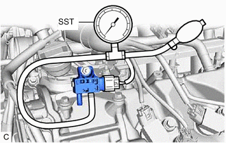
Slide the clip and disconnect the No. 2 vacuum transmitting hose assembly from the differential pressure sensor assembly.
-
Connect SST to the differential pressure sensor assembly.
-
Using SST, apply pressure to the differential pressure sensor assembly.
-
Check the pressure value of the differential pressure sensor assembly.
Standard GTS Display Condition Specified Condition GPF Defferential Pressure Offset Bank 1 Engine switch on (IG) When applying 20 kPa (2.9 psi): 20 kPa (2.9 psi)
When applying 40 kPa (5.8 psi): 40 kPa (5.8 psi)
Note:Perform the inspection within the range of 0 to 98 kPa (0 to 14.2 psi).
-
Disconnect SST from the differential pressure sensor assembly.
-
Connect the No. 2 vacuum transmitting hose assembly to the differential pressure sensor assembly and slide the clip to secure it.
Result Proceed to OK NG -
-
for Bank 2 side:
-
Enter the following menus: Powertrain / Engine and ECT / Data List / GPF Defferential Pressure Offset Bank 2.
- Powertrain > Engine > Data List
Tester Display GPF Differential Pressure Offset Bank2 -
-
-
-
- Powertrain > Engine > Data List
-
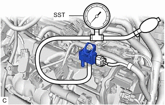
Slide the clip and disconnect the No. 1 vacuum transmitting hose assembly from the differential pressure sensor assembly.
-
Connect SST to the differential pressure sensor assembly.
-
Using SST, apply pressure to the differential pressure sensor assembly.
-
Check the pressure value of the differential pressure sensor assembly.
Standard GTS Display Condition Specified Condition GPF Defferential Pressure Offset Bank 2 Engine switch on (IG) When applying 20 kPa (2.9 psi): 20 kPa (2.9 psi)
When applying 40 kPa (5.8 psi): 40 kPa (5.8 psi)
Note:Perform the inspection within the range of 0 to 98 kPa (0 to 14.2 psi).
-
Disconnect SST from the differential pressure sensor assembly.
-
Connect the No. 1 vacuum transmitting hose assembly to the differential pressure sensor assembly and slide the clip to secure it.
-
-
Install the V-bank cover sub-assembly.
- OKClick here
- NGClick here
-
- Click here
READ VALUE USING GTS (MAF)
-
Connect the GTS to the DLC3.
-
Start the engine.
-
Turn the GTS on.
-
Enter the following menus: Powertrain / Engine / Data List / MAF.
-
Allow the engine to idle until Coolant Temperature reaches 75°C (167°F) or higher.
-
Read Mass Air Flow Sensor while maintaining an engine speed of 3000 rpm.
Standard GTS Display Condition Specified Condition MAF Engine warmed up
Shift position: P
A/C: Off
Engine Speed: 3000 rpm
Between 17.0 and 23.0 gm/sec Tip:When replacing the front exhaust pipe assembly, make sure to perform GPF Deposition Values Clear.
Result Proceed to OK NG
- OK
REPLACE FRONT EXHAUST PIPE ASSEMBLYClick here
- NG
REPAIR OR REPLACE MASS AIR FLOW METER SUB-ASSEMBLY CIRCUITClick here
-
- Click here
CHECK HARNESS AND CONNECTOR (DIFFERENTIAL PRESSURE SENSOR - ECM)
-
Disconnect the differential pressure sensor connector.
-
Disconnect the ECM connector.
-
Measure the resistance according to the value(s) in the table below.
Standard Resistance (for RHD) Tester Connection Condition Specified Condition F58-2 (PEX) - F2-32 (PEX) Always Below 1 Ω F58-1 (E2) - F2-24 (E2) Always Below 1 Ω F59-2 (PEX2) - F7-30 (PEX2) Always Below 1 Ω F59-1 (E2) - F2-24 (E2) Always Below 1 Ω F58-2 (PEX) or F2-32 (PEX) - Body ground and other terminals Always 10 kΩ or higher F58-3 (VC) or F2-26 (VC) - Body ground and other terminals Always 10 kΩ or higher F59-2 (PEX2) or F7-30 (PEX2) - Body ground and other terminals Always 10 kΩ or higher F59-3 (VC) or F2-26 (VC) - Body ground and other terminals Always 10 kΩ or higher Standard Resistance (for LHD) Tester Connection Condition Specified Condition F60-2 (PEX) - F2-32 (PEX) Always Below 1 Ω F60-1 (E2) - F2-24 (E2) Always Below 1 Ω F59-2 (PEX2) - F7-30 (PEX2) Always Below 1 Ω F59-1 (E2) - F2-24 (E2) Always Below 1 Ω F60-2 (PEX) or F2-32 (PEX) - Body ground and other terminals Always 10 kΩ or higher F60-3 (VC) or F2-26 (VC) - Body ground and other terminals Always 10 kΩ or higher F59-2 (PEX2) or F7-30 (PEX2) - Body ground and other terminals Always 10 kΩ or higher F59-3 (VC) or F2-26 (VC) - Body ground and other terminals Always 10 kΩ or higher Result Proceed to OK NG
- OK
REPLACE DIFFERENTIAL PRESSURE SENSORClick here
- NG
REPAIR OR REPLACE HARNESS OR CONNECTOR
-