CYLINDER HEAD REPLACEMENT

CAUTION / NOTICE / HINT
Tech Tips
-
Use the same procedure for the Bank 2 side and Bank 1 side.
-
The following procedure is for the Bank 1 side.
PROCEDURE
-
REPLACE INTAKE VALVE GUIDE BUSH
-
Heat the cylinder head LH to 80 to 100°C (176 to 212°F).
-
Place the cylinder head LH on wooden blocks.
CAUTION:
Be sure to wear protective gloves.
-
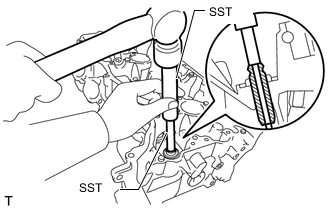
Using SST and a hammer, tap out the intake valve guide bush.
- SST
- 09201-10000 ( 09201-01050 )
- 09950-70010 ( 09951-07100 )
-
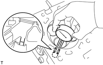
Using a caliper gauge, measure the intake valve guide bush bore diameter of the cylinder head LH.
Standard Bush Bore Diameter 10.285 to 10.306 mm (0.405 to 0.406 in.) If the intake valve guide bush bore diameter of the cylinder head LH is more than 10.306 mm (0.4057 in.), machine the bush bore to a dimension of 10.335 to 10.356 mm (0.4069 to 0.4077 in.) to install an O/S 0.05 intake valve guide bush.
If the bush bore diameter is 10.356 mm (0.408 in.) or more, replace the cylinder head LH.
-
Select a new intake valve guide bush (STD or O/S 0.05), and measure its diameter.
-
Machine the bush bore to a diameter of the selected intake valve guide bush.
Bush Bore Diameter Bush Size Bush Bore Diameter STD 10.285 to 10.306 mm
(0.405 to 0.406 in.)
O/S 0.05 10.335 to 10.356 mm
(0.407 to 0.408 in.)
-
Heat the cylinder head LH to 80 to 100°C (176 to 212°F).
CAUTION:
Be sure to wear protective gloves.
-
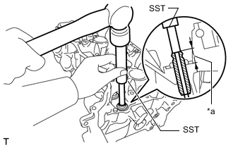
*a Height Using SST and a hammer, tap in a new intake valve guide bush to the specified protrusion height.
- SST
- 09201-10000 ( 09201-01050 )
- 09950-70010 ( 09951-07100 )
Standard Protrusion Height 14.3 to 14.7 mm (0.563 to 0.579 in.) -
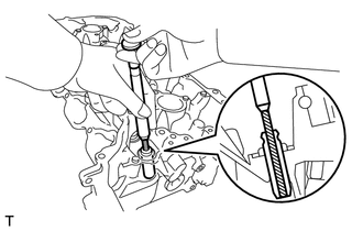
Using a sharp 5.5 mm reamer, ream the intake valve guide bush to obtain the specified clearance between the intake valve guide bush and valve stem.
-
-
REPLACE EXHAUST VALVE GUIDE BUSH
-
Heat the cylinder head LH to 80 to 100°C (176 to 212°F).
-
Place the cylinder head LH on wooden blocks.
CAUTION:
Be sure to wear protective gloves.
-
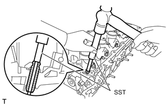
Using SST and a hammer, tap out the exhaust valve guide bush.
- SST
- 09201-10000 ( 09201-01050 )
- 09950-70010 ( 09951-07100 )
-
Using a caliper gauge, measure the exhaust valve guide bush bore diameter of the cylinder head LH.
Standard Cylinder Bore Diameter 10.285 to 10.306 mm (0.405 to 0.406 in.) If the exhaust valve guide bush bore diameter of the cylinder head LH is more than 10.306 mm (0.406 in.), machine the bush bore to a dimension of 10.335 to 10.356 mm (0.407 to 0.408 in.) to install an O/S 0.05 exhaust valve guide bush.
If the exhaust valve guide bush bore diameter of the cylinder head LH is more than 10.356 mm (0.408 in.), replace the cylinder head LH.
-
Select a new exhaust valve guide bush (STD or O/S 0.05), and measure its diameter.
-
Machine the bush bore diameter to a diameter of the selected exhaust valve guide bush.
Bush Bore Diameter Bush Size Bush Bore Diameter STD 10.285 to 10.306 mm
(0.4049 to 0.4057 in.)
O/S 0.05 10.335 to 10.356 mm
(0.4069 to 0.4077 in.)
-
Heat the cylinder head LH to 80 to 100°C (176 to 212°F).
CAUTION:
Be sure to wear protective gloves.
-
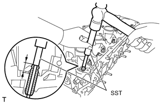
Using SST and a hammer, tap in a new exhaust valve guide bush to the specified protrusion height.
- SST
- 09201-10000 ( 09201-01050 )
- 09950-70010 ( 09951-07100 )
Standard Protrusion Height 14.3 to 14.7 mm (0.563 to 0.579 in.) -
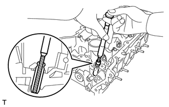
Using a sharp 5.5 mm reamer, ream the exhaust valve guide bush to obtain the specified clearance between the exhaust valve guide bush and valve stem.
-
-
REPLACE STRAIGHT PIN
Note
It is not necessary to remove the straight pins unless they are being replaced.
-
Using a plastic hammer, tap in new straight pins to the specified protrusion height.
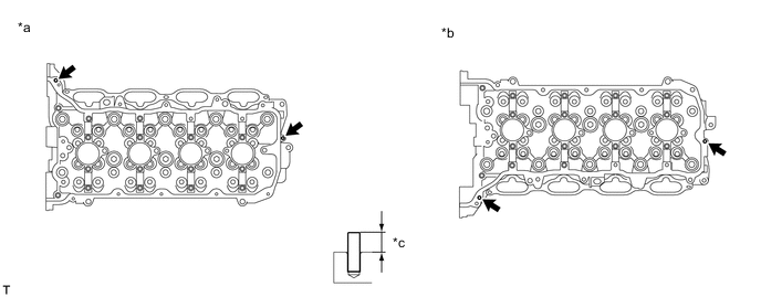
*a for Bank 1 *b for Bank 2 *c Protrusion height - - Standard Protrusion Height 8.0 to 10.0 (0.315 to 0.394 in.)
-
-
REPLACE STUD BOLT
Note
If a stud bolt is deformed or its threads are damaged, replace it.
-
Using E6 and E8 "TORX" socket wrenches, install the stud bolts.
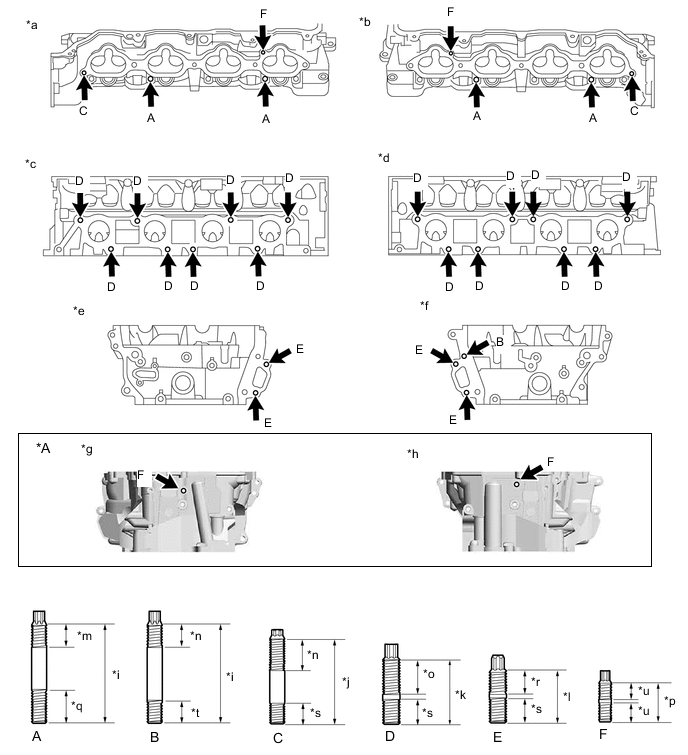
*A w/ Differential Pressure Sensor - - *a for Bank 2 Intake Side *b for Bank 1 Intake Side *c for Bank 2 Exhaust Side *d for Bank 1 Exhaust Side *e for Bank 2 Front Side *f for Bank 1 Front Side *g for Bank 2 Rear Side *h for Bank 1 Rear Side *i 52 mm (2.05 in.) *j 45 mm (1.77 in.) *k 35 mm (1.38 in.) *l 29 mm (1.14 in.) *m 26 mm (1.02 in.) *n 24 mm (0.945 in.) *o 20 mm (0.787 in.) *p 19 mm (0.748 in.) *q 17 mm (0.669 in.) *r 14 mm (0.551 in.) *s 13 mm (0.512 in.) *t 12 mm (0.472 in.) *u 9 mm (0.354 in.) - - - Torque:
- Stud Bolt (A), (B), (C), (D) and (E)
- 9.0 N*m { 92 kgf*cm, 80 in.*lbf }
- Stud Bolt (F)
- 5.0 N*m { 51 kgf*cm, 44 in.*lbf }
-