CYLINDER HEAD REASSEMBLY

CAUTION / NOTICE / HINT
Tech Tips
-
Use the same procedure for bank 1 and bank 2.
-
The following procedure is for bank 2.
PROCEDURE
-
INSTALL NO. 2 STRAIGHT SCREW PLUG
-
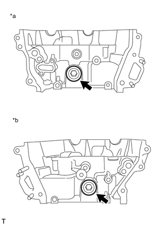
*a for Bank 1 *b for Bank 2 Using a 14 mm hexagon socket wrench, install 2 new screw plug gaskets and the 2 No. 2 straight screw plugs.
- Torque:
- 80 N*m { 816 kgf*cm, 59 ft.*lbf }
-
-
INSTALL NO. 1 STRAIGHT SCREW PLUG
-
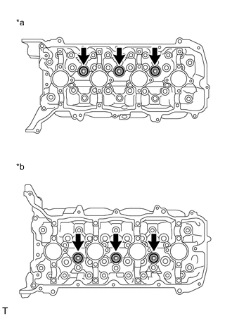
*a for Bank 1 *b for Bank 2 Apply adhesive to the No. 1 straight screw plug.
Adhesive Toyota Genuine Adhesive 1324, Three Bond 1324 or equivalent Note
Install the No. 1 straight screw plug within 3 minutes of applying adhesive.
-
Using a 10 mm hexagon socket wrench, install 6 new screw plug gaskets and the 6 No. 1 straight screw plugs.
- Torque:
- 44 N*m { 449 kgf*cm, 32 ft.*lbf }
Note
Do not add engine oil for at least 1 hour after installation.
-
-
INSTALL VALVE SPRING SEAT
-
Install the 16 valve spring seats to the cylinder head LH.
-
-
INSTALL INTAKE VALVE STEM OIL SEAL
-
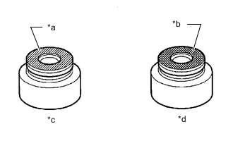
*a Gray *b Black *c Intake Side *d Exhaust Side Apply a light coat of engine oil to new intake valve stem oil seals.
Note
Pay attention when installing the intake valve stem oil seals.
Installing the intake valve stem oil seals to the wrong valve guide bush may cause installation problems later.
Tech Tips
The intake valve stem oil seals are gray and the exhaust valve stem oil seals are black.
-

*1 Intake Valve Stem Oil Seal *a Correct *b Incorrect Using SST, push in the intake valve stem oil seals.
- SST
- 09201-41020
Note
-
Failure to use SST will cause the intake valve stem oil seal to be damaged or improperly seated.
-
-
INSTALL EXHAUST VALVE STEM OIL SEAL
Tech Tips
Use the same procedure as for the intake side.
-
INSTALL INTAKE VALVE
Tech Tips
-
Select the inner compression springs and valve spring retainers based on the identification mark on the cylinder head.
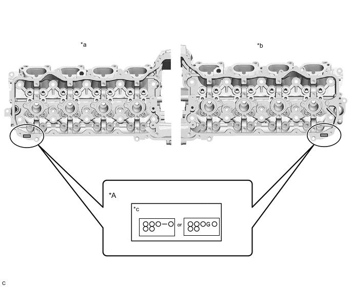
*A Type A - - *a Cylinder Head Sub-assembly *b Cylinder Head LH *c Identification Mark - - -
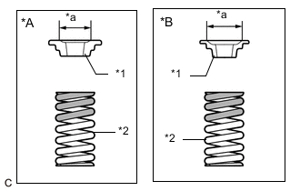
*A Type A *B except Type A *1 Valve Spring Retainer *2 Inner Compression Spring *a Diameter 
Paint Mark There are 2 types of inner compression springs and valve spring retainers. The 2 types are not interchangeable.
Type Valve Spring Retainer Diameter Inner Compression Spring Paint Mark A 14 mm (0.551 in.) Intake Side: Pink
Exhaust Side: Light Green
except A 16.8 mm (0.661 in.) Intake Side: Orange
Exhaust Side: Light Blue
-
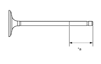
*a 40 mm (1.57 in.) or more Sufficiently apply engine oil to the tip area of the intake valve shown in the illustration.
-
Install the intake valve, inner compression spring and valve spring retainer to the cylinder head.
Note
Install the same parts in the same combination to their original locations.
-
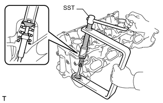
Using SST and wooden blocks, compress the inner compression spring and install the valve spring retainer lock.
- SST
- 09202-70020 ( 09202-00010, 09202-01010, 09202-01020 )
Note
Install the same parts in the same combination to their original locations.
-
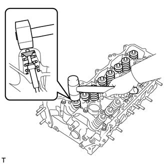
Using a plastic hammer, lightly tap the valve stem tip to ensure a proper fit.
Note
Be careful not to damage the valve spring retainer.
-
-
INSTALL EXHAUST VALVE
Tech Tips
-
Select the inner compression springs and valve spring retainers based on the identification mark on the cylinder head.
*A Type A - - *a Cylinder Head Sub-assembly *b Cylinder Head LH *c Identification Mark - - -
*A Type A *B except Type A *1 Valve Spring Retainer *2 Inner Compression Spring *a Diameter Paint Mark There are 2 types of inner compression springs and valve spring retainers. The 2 types are not interchangeable.
Type Valve Spring Retainer Diameter Inner Compression Spring Paint Mark A 14 mm (0.551 in.) Intake Side: Pink
Exhaust Side: Light Green
except A 16.8 mm (0.661 in.) Intake Side: Orange
Exhaust Side: Light Blue
-
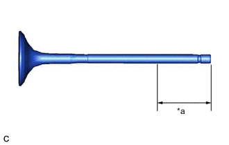
*a 40 mm (1.57 in.) or more Sufficiently apply engine oil to the tip area of the exhaust valve shown in the illustration.
-
Install the exhaust valve, inner compression spring and valve spring retainer to the cylinder head.
Note
Install the same parts in the same combination to their original locations.
-
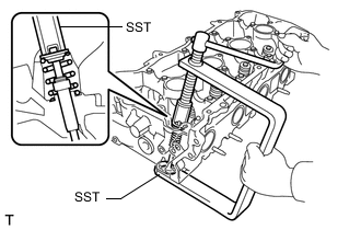
Using SST, compress the inner compression spring and install the valve spring retainer lock.
- SST
- 09202-70020 ( 09202-00010, 09202-01010, 09202-01020 )
Note
Install the same parts in the same combination to their original locations.
-
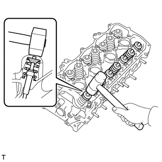
Using a plastic hammer, lightly tap the valve stem tip to ensure a proper fit.
Note
Be careful not to damage the valve spring retainer.
-
-
INSTALL VALVE ADJUSTING SHIM
-
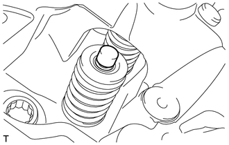
Apply a light coat of engine oil to the 16 valve adjusting shims.
-
Install the 16 valve adjusting shims.
-