AUTOMATIC HIGH BEAM MAIN SWITCH INSPECTION
PROCEDURE
-
INSPECT AUTOMATIC HIGH BEAM MAIN SWITCH (NO. 2 COMBINATION SWITCH ASSEMBLY)
-
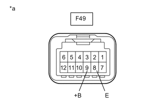
*a Component without harness connected
(Automatic High Beam Main Switch (No. 2 Combination Switch Assembly))
Measure the resistance according to the value(s) in the table below.
Standard Resistance Tester Connection Condition Specified Condition F49-9 (+B) - F49-8 (E) Automatic high beam main switch (No. 2 combination switch assembly) not pressed 1 MΩ or higher F49-9 (+B) - F49-8 (E) Automatic high beam main switch (No. 2 combination switch assembly) pressed Below 25 Ω If the result is not as specified, replace the Automatic high beam main switch (No. 2 combination switch assembly).
-
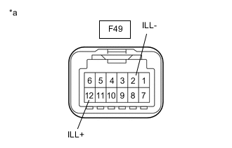
*a Component without harness connected
(Automatic High Beam Main Switch (No. 2 Combination Switch Assembly))
Illumination Inspection
-
Apply auxiliary battery voltage to the Automatic high beam main switch (No. 2 combination switch assembly) and check that the switch illuminates.
OK Tester Connection Specified Condition F49-12 (ILL+) - Auxiliary battery positive (+)
F49-2 (ILL-) - Auxiliary battery negative (-)
Illuminates If the result is not as specified, replace the Automatic high beam main switch (No. 2 combination switch assembly).
-
-