HAZARD WARNING SWITCH INSPECTION
PROCEDURE
-
INSPECT HAZARD WARNING SIGNAL SWITCH ASSEMBLY
-
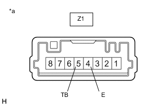
*a Component without harness connected
(Hazard Warning Signal Switch Assembly)
Measure the resistance according to the value(s) in the table below.
Standard Resistance Tester Connection Condition Specified Condition Z1-5 (TB) - Z1-4 (E) Hazard warning signal switch off 1 MΩ or higher Z1-5 (TB) - Z1-4 (E) Hazard warning signal switch on Below 50 Ω If the result is not as specified, replace the hazard warning signal switch assembly.
-
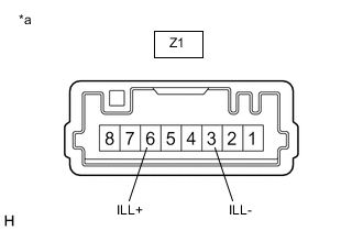
*a Component without harness connected
(Hazard Warning Signal Switch Assembly)
Illumination Inspection
-
Apply auxiliary battery voltage to the hazard warning signal switch assembly and check that the switch illuminates.
OK Tester Connection Specified Condition Z1-6 (ILL+) - Auxiliary battery positive (+)
Z1-3 (ILL-) - Auxiliary battery negative (-)
Illuminates If the result is not as specified, replace the hazard warning signal switch assembly.
-
-