AUTOMATIC HIGH BEAM SYSTEM TERMINALS OF ECU
-
CHECK INSTRUMENT PANEL JUNCTION BLOCK ASSEMBLY AND MAIN BODY ECU (MULTIPLEX NETWORK BODY ECU)
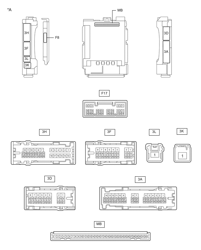
*A Main Body ECU (Multiplex Network Body ECU) with 1 Connector - - 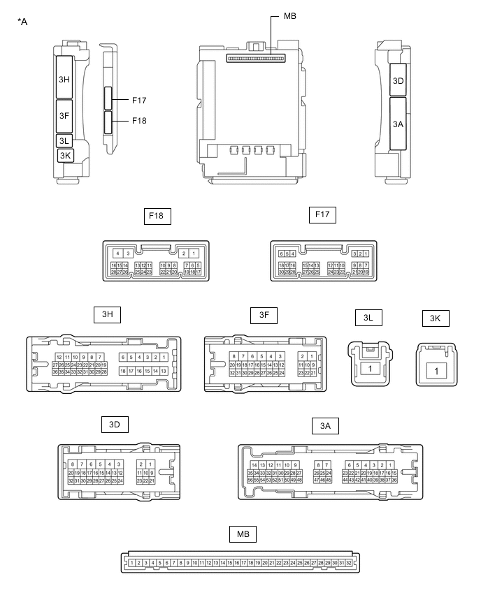
*A Main Body ECU (Multiplex Network Body ECU) with 2 Connectors - -
-
Measure the voltage and check for pulses according to the value(s) in the table below.
Terminal No. (Symbol) Wiring Color Terminal Description Condition Specified Condition 3F-31 - Body ground G - Body ground H-LP LH relay drive output Power switch off 11 to 14 V Power switch on (IG) Below 1 V F17-1 (DIM) - Body ground BE - Body ground H-LP RH relay drive output Power switch off 11 to 14 V Power switch on (IG) Below 1 V F17-8 (A) - Body ground W - Body ground Light control switch AUTO position signal input Light control switch in AUTO position Below 1 V Light control switch not in AUTO position Pulse generation F17-12 (HEAD) - Body ground G - Body ground Light control switch head position input Light control switch in head position Below 1 V Light control switch not in head position Pulse generation F17-20 (CLTS) - Body ground R - Body ground Automatic light control sensor signal input Power switch off Below 1 V Automatic light control system operating Communication waveform generation
(See waveform 1)
F17-19 (CLTB) - F17-21 (CLTE) BR - G Automatic light control sensor power supply output Power switch off Below 1 V Power switch on (IG) 11 to 14 V F17-24 (HU) - Body ground P - Body ground Dimmer switch high position signal input Dimmer switch in high position Below 1 V Dimmer switch not in high position Pulse generation F17-17 (AHBI) - Body ground B - Body ground Auto matic high beam main switch signal input Power switch on (IG), auto matic high beam main switch on Below 1 V Power switch on (IG), auto matic high beam main switch off 11 to 14 V If the result is not as specified, the main body ECU (multiplex network body ECU) or instrument panel junction block assembly may be malfunctioning.
-
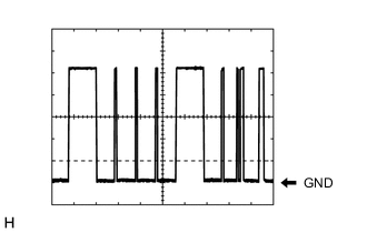
Waveform 1
Item Content Tool setting 2 V/DIV., 10 ms./DIV. Tech Tips
The communication waveform changes according to the surrounding brightness.
-
-
-
CHECK FORWARD RECOGNITION CAMERA