LIGHTING SYSTEM Clearance Light Circuit
DESCRIPTION
-
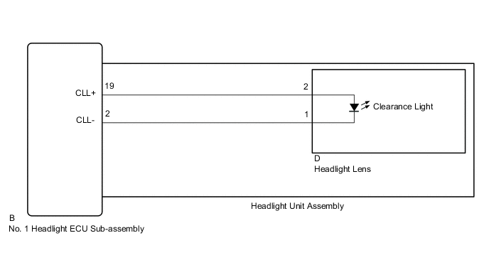
When the main body ECU (multiplex network body ECU) receives the light control switch position signal, it sends an illumination request signal to the No. 1 headlight ECU sub-assembly LH and illuminates the clearance lights.
Clearance light function:
WIRING DIAGRAM
CAUTION / NOTICE / HINT
Note
If the No. 1 headlight ECU sub-assembly LH has been replaced, it is necessary to synchronize the vehicle information and initialize the No. 1 headlight ECU sub-assembly LH.
PROCEDURE
-
PERFORM ACTIVE TEST USING GTS
-
Connect the GTS to the DLC3.
-
Turn the power switch on (IG).
-
Turn the GTS on.
-
Enter the following menus: Body Electrical / HL AutoLeveling / Active Test.
-
Perform the Active Test according to the display on the GTS.
Body Electrical > HL AutoLeveling > Active TestTester Display Measurement Item Control Range Diagnostic Note Clearance Light Clearance lights ON or OFF -
Body Electrical > HL AutoLeveling > Active TestTester Display Clearance Light OK Clearance lights illuminate. Result Result Proceed to OK A NG (for LH Side) B NG (for RH Side) C
A 
PROCEED TO NEXT SUSPECTED AREA SHOWN IN PROBLEM SYMPTOMS TABLE Click here
C 
INSPECT HEADLIGHT UNIT ASSEMBLY RH Click here
B 
-
-
INSPECT HEADLIGHT UNIT ASSEMBLY LH
-
Remove the headlight assembly LH.
-
Remove the headlight unit assembly LH from the headlight assembly LH.
-
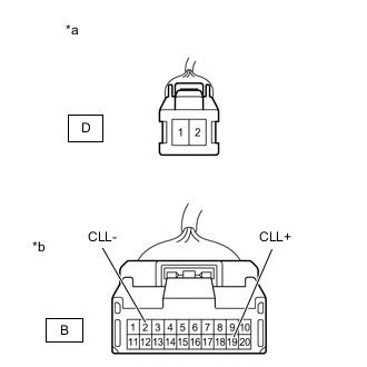
*a Component without harness connected
(to Headlight Lens LH)
*b Component without harness connected
(to No. 1 Headlight ECU Sub-assembly LH)
Measure the resistance according to the value(s) in the table below.
Standard Resistance Tester Connection Condition Specified Condition D-2 - B-19 (CLL+) Always Below 1 Ω D-1 - B-2 (CLL-) Always Below 1 Ω Result Result OK NG
NG
REPLACE HEADLIGHT UNIT ASSEMBLY LH Click here
OK
-
-
INSPECT HEADLIGHT LENS LH (CLEARANCE LIGHT)
-
Reconnect the D headlight lens LH connector.
-

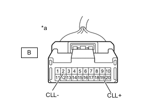
*a Component without harness connected
(to No. 1 Headlight ECU Sub-assembly LH)
Apply auxiliary battery voltage to the headlight lens LH and check that the light comes on.
OK Condition Specified Condition Auxiliary battery positive (+) → B-19 (CLL+)
Auxiliary battery negative (-) → B-2 (CLL-)
Clearance light comes on Result Proceed to OK NG
OK
REPLACE NO. 1 HEADLIGHT ECU SUB-ASSEMBLY LH Click here
NG
REPLACE HEADLIGHT LENS LH Click here
-
-
INSPECT HEADLIGHT UNIT ASSEMBLY RH
-
Remove the headlight assembly RH.
-
Remove the headlight unit assembly RH from the headlight assembly RH.
-
*a Component without harness connected
(to Headlight Lens RH)
*b Component without harness connected
(to No. 1 Headlight ECU Sub-assembly RH)
Measure the resistance according to the value(s) in the table below.
Standard Resistance Tester Connection Condition Specified Condition D-2 - B-19 (CLL+) Always Below 1 Ω D-1 - B-2 (CLL-) Always Below 1 Ω Result Result OK NG
NG
REPLACE HEADLIGHT UNIT ASSEMBLY RH Click here
OK
-
-
INSPECT HEADLIGHT LENS RH (CLEARANCE LIGHT)
-
Reconnect the D headlight lens RH connector.
-
*a Component without harness connected
(to No. 1 Headlight ECU Sub-assembly RH)
Apply auxiliary battery voltage to the headlight lens RH and check that the light comes on.
OK Condition Specified Condition Auxiliary battery positive (+) → B-19 (CLL+)
Auxiliary battery negative (-) → B-2 (CLL-)
Clearance light comes on Result Proceed to OK NG
OK
REPLACE NO. 1 HEADLIGHT ECU SUB-ASSEMBLY RH Click here
NG
REPLACE HEADLIGHT LENS RH Click here
-