BACK DOOR ADJUSTMENT
CAUTION / NOTICE / HINT
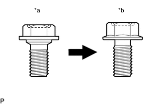
| *a | Centering Bolt |
| *b | Standard Bolt |
Tech Tips
-
Centering bolts are used to install the door hinges to the door. The door cannot be adjusted with the centering bolts installed. Substitute the centering bolts with standard bolts (with washers) when making adjustments.
-
The specified torque for standard bolts is shown in the standard bolt chart.
PROCEDURE
-
INSPECT BACK DOOR
-
Check that the clearance measurements of areas a through l are within each standard range.
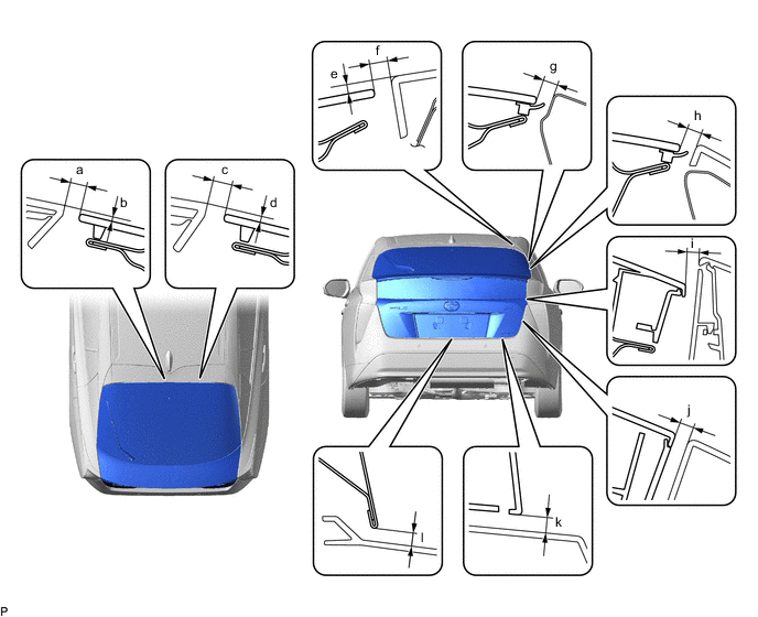
Standard Clearance Area Measurement Area Measurement a 4.6 to 9.6 mm (0.181 to 0.378 in.) b -0.5 to 4.5 mm (-0.0197 to 0.177 in.) c 4.6 to 9.6 mm (0.181 to 0.378 in.) d -0.5 to 4.5 mm (-0.0197 to 0.177 in.) e 4.6 to 9.6 mm (0.181 to 0.378 in.) f 1.0 to 6.0 mm (0.0394 to 0.236 in.) g 3.85 to 7.85 mm (0.152 to 0.309 in.) h 3.5 to 8.5 mm (0.138 to 0.335 in.) i 4.0 to 9.0 mm (0.157 to 0.354 in.) j 4.0 to 9.0 mm (0.157 to 0.354 in.) k 5.0 to 10.0 mm (0.197 to 0.394 in.) l 4.35 to 8.35 mm (0.171 to 0.329 in.)
-
-
REMOVE DECK TRIM SERVICE HOLE COVER
-
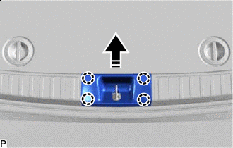

Remove in this Direction Disengage the 4 claws to remove the deck trim service hole cover as shown in the illustration.
-
-
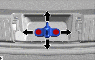
ADJUST BACK DOOR
-
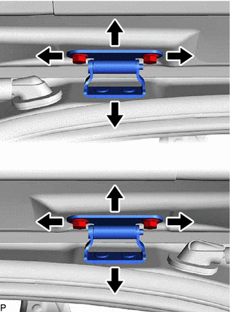
Loosen the 4 hinge bolts on the back door and adjust the back door position.
-
Tighten the 4 hinge bolts on the back door after adjustment.
- Torque:
- 19 N*m { 194 kgf*cm, 14 ft.*lbf }
-
Using a T40 "TORX" socket wrench, slightly loosen the 2 striker mounting screws.
-
Using a brass bar and a hammer, hit the striker to adjust its position.
-
Using a T40 "TORX" socket wrench, tighten the 2 striker mounting screws after adjustment.
- Torque:
- 23 N*m { 235 kgf*cm, 17 ft.*lbf }
-
-
INSTALL DECK TRIM SERVICE HOLE COVER
-
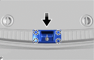
Install in this Direction Engage the 4 claws to install the deck trim service hole cover as shown in the illustration.
-