ROOF HEADLINING REMOVAL
PROCEDURE
-
REMOVE TONNEAU COVER ASSEMBLY
-
Remove the tonneau cover assembly.
-
-
REMOVE REAR NO. 1 FLOOR BOARD
-
Remove the rear No. 1 floor board.
-
-
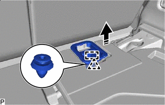
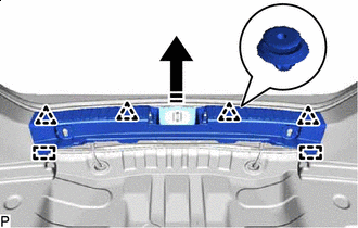
REMOVE DECK BOARD RETAINER
-


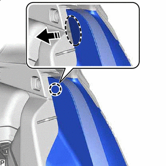
Remove in this Direction for LH Side:
-
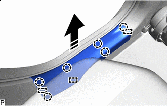
Disengage the clip and guide to remove the deck board retainer as shown in the illustration.
-
-
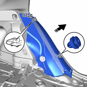
Remove in this Direction for RH Side:
-
Disengage the clip and guide to remove the deck board retainer as shown in the illustration.
-
-
-
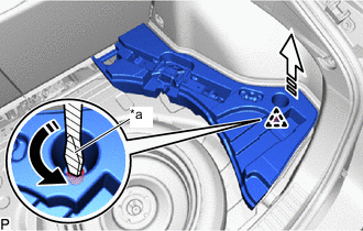
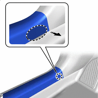
REMOVE DECK FLOOR BOX LH (w/o Spare Tire)
-
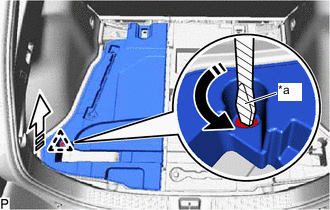
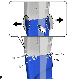
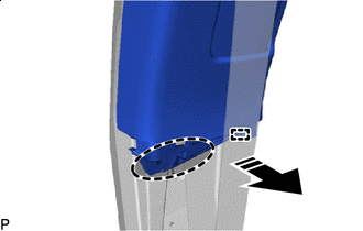
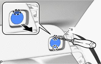
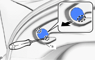
*a Protective Tape Turn in this Direction 
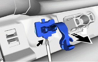
Remove in this Direction Using a screwdriver with its tip wrapped with protective tape, while pulling the deck floor box LH as shown in the illustration, turn the clip to remove the deck floor box LH.
-
-
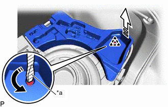
REMOVE DECK FLOOR BOX RH (w/o Spare Tire)
-
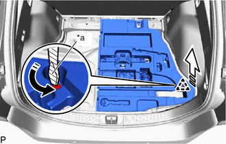
*a Protective Tape Turn in this Direction Remove in this Direction Using a screwdriver with its tip wrapped with protective tape, while pulling the deck floor box RH as shown in the illustration, turn the clip to remove the deck floor box RH.
-
-
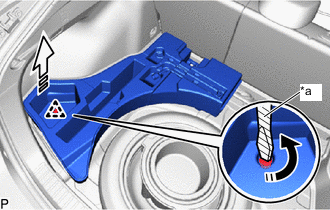
REMOVE REAR DECK FLOOR BOX (w/ Compact Spare Tire)
-
Remove the rear deck floor box.
-
-
REMOVE DECK FLOOR BOX LH (w/ Compact Spare Tire)
-
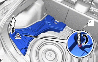
*a Protective Tape Turn in this Direction Remove in this Direction Using a screwdriver with its tip wrapped with protective tape, while pulling the deck floor box LH as shown in the illustration, turn the clip to remove the deck floor box LH.
-
-
REMOVE DECK FLOOR BOX RH (w/ Compact Spare Tire)
-
*a Protective Tape Turn in this Direction Remove in this Direction Using a screwdriver with its tip wrapped with protective tape, while pulling the deck floor box RH as shown in the illustration, turn the clip to remove the deck floor box RH.
-
-
REMOVE DECK FLOOR BOX RH (w/ Full Size Spare Tire)
-
*a Protective Tape Turn in this Direction Remove in this Direction Using a screwdriver with its tip wrapped with protective tape, while pulling the deck floor box RH as shown in the illustration, turn the clip to remove the deck floor box RH.
-
-
REMOVE DECK FLOOR BOX LH (w/ Full Size Spare Tire)
-
*a Protective Tape Turn in this Direction Remove in this Direction Using a screwdriver with its tip wrapped with protective tape, while pulling the deck floor box LH as shown in the illustration, turn the clip to remove the deck floor box LH.
-
-
REMOVE DECK TRIM SERVICE HOLE COVER
-
REMOVE LUGGAGE HOLD BELT STRIKER ASSEMBLY (for Rear Side)
-
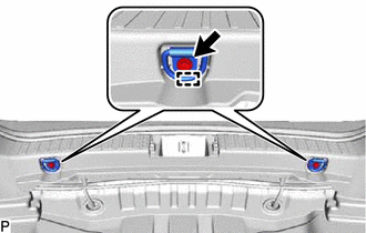
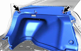
Remove the 2 bolts.
-
Disengage the 2 guides to remove the 2 luggage hold belt striker assemblies.
-
-
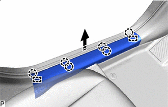
REMOVE REAR DECK TRIM COVER
-
Remove in this Direction Disengage the 4 clips and 2 guides to remove the rear deck trim cover as shown in the illustration.
-
-
REMOVE FRONT DOOR SCUFF PLATE LH
-

Place Hand Here Remove in this Direction Disengage the claw as shown in the illustration.
Tech Tips
Use the same procedure for the front side and rear side.
-
Remove in this Direction Disengage the 6 claws and 2 guides to remove the front door scuff plate LH as shown in the illustration.
-
-
REMOVE COWL SIDE TRIM BOARD LH
-
Remove in this Direction Remove the clip.
-
Disengage the 2 clips to remove the cowl side trim board LH as shown in the illustration.
-
-
REMOVE FRONT DOOR OPENING TRIM WEATHERSTRIP LH
-
REMOVE FRONT PILLAR GARNISH LH
-
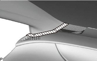

Protective Tape Apply protective tape around the front pillar garnish LH as shown in the illustration.
-
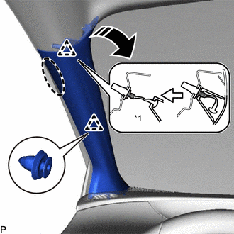
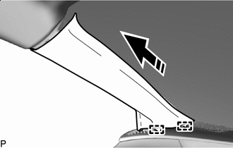
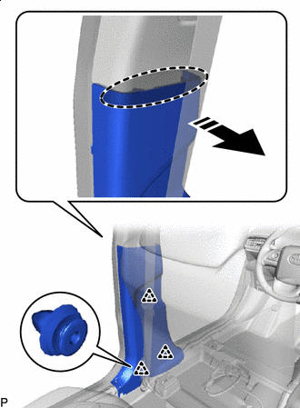
*1 Front Pillar Garnish Clip Place Hand Here Remove in this Direction Pull the upper part of the front pillar garnish LH toward the inside of the cabin to disengage the clip and the front pillar garnish LH from the base of the front pillar garnish clip.
Tech Tips
Let the front pillar garnish LH hang from the front pillar garnish clip.
-
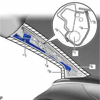
*1 Front Pillar Garnish Clip Remove in this Direction While pushing the tabs of the front pillar garnish clip as shown in the illustration, disengage it.
Note
The front pillar garnish clip is reusable if it is not damaged.
-
When the front pillar garnish clip cannot be removed using your fingers:
-
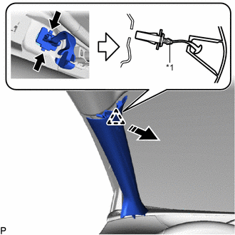
Lift in this Direction (1) While pressing the part shown in the illustration with your finger, move the front pillar garnish clip in the direction indicated by the arrow (1) shown in the illustration.
-
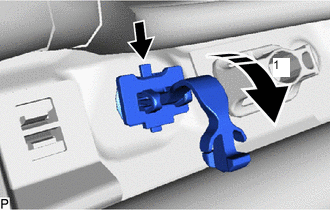
Pull in this Direction (2) While pulling the front pillar garnish clip in the direction indicated by the arrow (2), push the part shown in the illustration with the end of a screwdriver and remove the front pillar garnish clip.
Note
If the front pillar garnish clip is damaged, replace it with a new one.
-
-
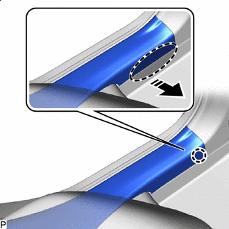
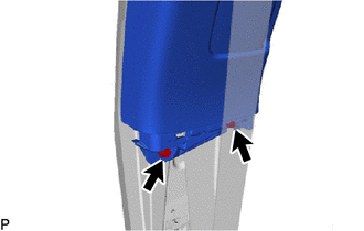
Remove in this Direction Disengage the 2 guides to remove the front pillar garnish LH as shown in the illustration.
-
*1 Curtain Shield Airbag Assembly LH *a Protective Cover *b Adhesive Tape Protect the curtain shield airbag assembly LH.
-
Cover the curtain shield airbag assembly LH with a piece of cloth or nylon and secure the edges of the cover with tape as shown in the illustration.
Note
Cover the curtain shield airbag assembly LH with a protective cover as soon as the front pillar garnish LH is removed.
-
-
-
REMOVE REAR DOOR SCUFF PLATE LH
-
Place Hand Here Remove in this Direction Disengage the claw as shown in the illustration.
-
Remove in this Direction Disengage the 6 claws and 3 guides to remove the rear door scuff plate LH as shown in the illustration.
-
-
REMOVE REAR DOOR OPENING TRIM WEATHERSTRIP LH
-
REMOVE LAP BELT OUTER ANCHOR COVER (for LH Side)
-
DISCONNECT FRONT SEAT OUTER BELT ASSEMBLY LH
-
REMOVE LOWER CENTER PILLAR GARNISH LH
-
*a Claw (A) *b Claw (B) Place Hand Here Remove in this Direction (1) Remove in this Direction (2) Pull the lower center pillar garnish LH in the directions indicated by the arrows (1) shown in the illustration to disengage the 2 claws (A).
-
Pull the lower center pillar garnish LH in the direction indicated by the arrow (2) shown in the illustration to disengage the 2 claws (B).
-
Place Hand Here Remove in this Direction Disengage the 3 clips to remove the lower center pillar garnish LH as shown in the illustration.
-
-
REMOVE CENTER PILLAR GARNISH ASSEMBLY LH
-
Using a clip remover, remove the 2 clips.
-
Place Hand Here Remove in this Direction Disengage the guide as shown in the illustration.
-
Place Hand Here Remove in this Direction Disengage the clip and 2 guides to remove the center pillar garnish assembly LH as shown in the illustration.
-
-
REMOVE FRONT DOOR SCUFF PLATE RH
Tech Tips
Use the same procedure as for the LH side.
-
REMOVE COWL SIDE TRIM BOARD RH
Tech Tips
Use the same procedure as for the LH side.
-
REMOVE FRONT DOOR OPENING TRIM WEATHERSTRIP RH
Tech Tips
Use the same procedure as for the LH side.
-
REMOVE FRONT PILLAR GARNISH RH
Tech Tips
Use the same procedure as for the LH side.
-
REMOVE REAR DOOR SCUFF PLATE RH
Tech Tips
Use the same procedure as for the LH side.
-
REMOVE REAR DOOR OPENING TRIM WEATHERSTRIP RH
Tech Tips
Use the same procedure as for the LH side.
-
REMOVE LAP BELT OUTER ANCHOR COVER (for RH Side)
Tech Tips
Use the same procedure as for the LH side.
-
DISCONNECT FRONT SEAT OUTER BELT ASSEMBLY RH
Tech Tips
Use the same procedure as for the LH side.
-
REMOVE LOWER CENTER PILLAR GARNISH RH
Tech Tips
Use the same procedure as for the LH side.
-
REMOVE CENTER PILLAR GARNISH ASSEMBLY RH
Tech Tips
Use the same procedure as for the LH side.
-
REMOVE REAR SEAT ASSEMBLY
-
REMOVE REAR UNDER SIDE COVER LH
-
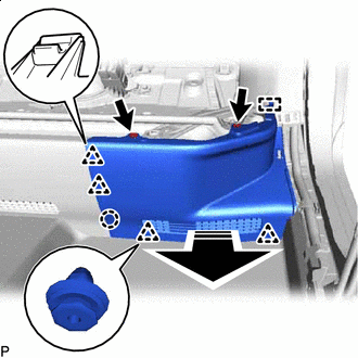
Remove in this Direction Remove the 2 clips.
-
Disengage the claw, 4 clips and guide to remove the rear under side cover LH as shown in the illustration.
-
-
REMOVE REAR SEATBACK HINGE SUB-ASSEMBLY LH
-
Loosen the bolt to remove the rear seatback hinge sub-assembly LH.
-
-
REMOVE REAR SEAT SIDE GARNISH LH
-
Place Hand Here Remove in this Direction Disengage the claw as shown in the illustration.
-
Remove in this Direction Disengage the 2 clips and 2 guides to remove the rear seat side garnish LH as shown in the illustration.
-
-
REMOVE LUGGAGE HOLD BELT STRIKER ASSEMBLY (for LH Side)
-
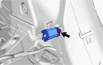
Remove the bolt.
-
Disengage the guide to remove the luggage hold belt striker assembly.
-
-
REMOVE NO. 1 TONNEAU COVER HOLDER CAP (for LH Side)
-
*a Protective Tape Insert Screwdriver Here Remove in this Direction Using a screwdriver with its tip wrapped with protective tape, disengage the 2 claws to remove the No. 1 tonneau cover holder cap as shown in the illustration.
-
-
REMOVE TONNEAU COVER HOOK A (for LH Side)
-
*a Protective Tape Insert Screwdriver Here Remove in this Direction Using a screwdriver with its tip wrapped with protective tape, disengage the 2 claws to remove the tonneau cover hook A as shown in the illustration.
-
-
REMOVE NO. 1 LUGGAGE COMPARTMENT LIGHT ASSEMBLY
-
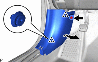
REMOVE DECK TRIM SIDE PANEL ASSEMBLY LH
-
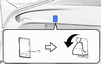
*1 No. 2 Luggage Compartment Trim Hook Lower the No. 2 luggage compartment trim hook as shown in the illustration.
-
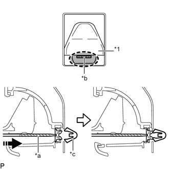
*1 No. 2 Luggage Compartment Trim Hook *a Protective Tape *b Hole (A) *c Clip Insert Screwdriver Here Push in this Direction Using a screwdriver with its tip wrapped with protective tape, disengage the clip as shown in the illustration.
Tech Tips
Insert the screwdriver into the hole (A).
-
Remove the 2 screws.
-
Disengage the 5 claws, 2 clips and guide to remove the deck trim side panel assembly LH as shown in the illustration.
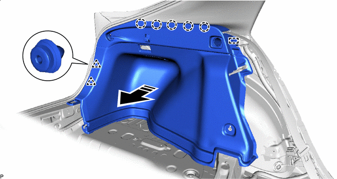
Remove in this Direction - -
-
-
REMOVE ROOF SIDE INNER GARNISH ASSEMBLY LH
-
Disengage the 5 clips as shown in the illustration to remove the roof side inner garnish assembly LH.
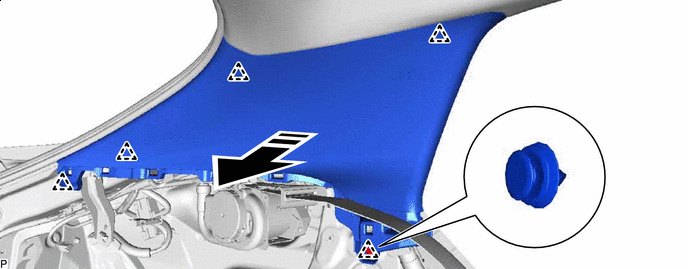
Remove in this Direction - -
-
-
REMOVE REAR UNDER SIDE COVER RH
Tech Tips
Use the same procedure as for the LH side.
-
REMOVE REAR SEATBACK HINGE SUB-ASSEMBLY RH
Tech Tips
Use the same procedure as for the LH side.
-
REMOVE REAR SEAT SIDE GARNISH RH
Tech Tips
Use the same procedure as for the LH side.
-
REMOVE LUGGAGE HOLD BELT STRIKER ASSEMBLY (for RH Side)
Tech Tips
Use the same procedure as for the LH side.
-
REMOVE NO. 1 TONNEAU COVER HOLDER CAP (for RH Side)
Tech Tips
Use the same procedure as for the LH side.
-
REMOVE TONNEAU COVER HOOK A (for RH Side)
Tech Tips
Use the same procedure as for the LH side.
-
REMOVE DECK TRIM SIDE PANEL ASSEMBLY RH
Tech Tips
Use the same procedure as for the LH side.
-
REMOVE ROOF SIDE INNER GARNISH ASSEMBLY RH
Tech Tips
Use the same procedure as for the LH side.
-
REMOVE ROOF CONSOLE BOX ASSEMBLY
-
REMOVE NO. 1 ROOM LIGHT ASSEMBLY
-
REMOVE SENSOR COVER (w/ Humidity Sensor)
-
REMOVE AIR CONDITIONING THERMISTOR ASSEMBLY (w/ Humidity Sensor)
-
REMOVE RAIN SENSOR COVER (w/ Rain Sensor)
-
REMOVE RAIN SENSOR (w/ Rain Sensor)
-
REMOVE INNER REAR VIEW MIRROR STAY HOLDER COVER (w/ Inner Rear View Mirror Stay Holder Cover)
-
REMOVE NO. 2 FORWARD RECOGNITION COVER (w/ Toyota Safety Sense)
-
REMOVE NO. 1 FORWARD RECOGNITION COVER (w/ Toyota Safety Sense)
-
REMOVE ASSIST GRIP ASSEMBLY
Tech Tips
Use the same procedure for all assist grip assemblies.
-
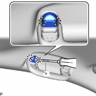
*a Protective Tape Insert Screwdriver Here Using a screwdriver with its tip wrapped with protective tape, disengage the 2 claws and remove the assist grip cover LH.
Tech Tips
Use the same procedure for the RH side and LH side.
-
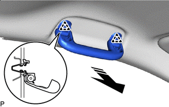
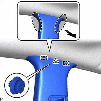
Remove in this Direction Disengage the 2 clips as shown in the illustration to remove the assist grip assembly.
-
Remove the 2 clips from the vehicle body.
-
-
REMOVE REAR ASSIST GRIP ASSEMBLY LH
Tech Tips
Use the same procedure as for the assist grip assembly.
-
REMOVE REAR ASSIST GRIP ASSEMBLY RH
Tech Tips
Use the same procedure as for the assist grip assembly.
-
REMOVE VISOR BRACKET COVER (for LH Side)
-
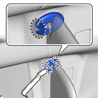
Insert Moulding Remover Here Using a moulding remover, disengage the 4 claws as shown in the illustration and remove the visor bracket cover.
-
-
REMOVE VISOR ASSEMBLY LH
-
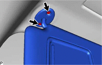
Remove the 2 screws.
-
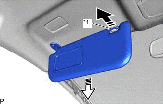
*1 Visor Holder Remove in this Direction (1) Remove in this Direction (2) Pull the visor assembly LH in the direction indicated by the arrow (1) shown in the illustration to disconnect it from the visor holder.
-
Pull the visor assembly LH in the direction indicated by the arrow (2) shown in the illustration to remove it.
-
-
REMOVE VISOR HOLDER LH
-
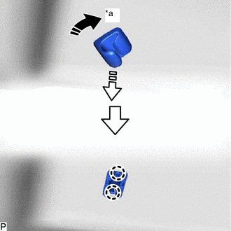
*a 45° Remove in this Direction (1) Remove in this Direction (2) Turn the visor holder approximately 45° and pull it out as indicated by the arrows, in the order shown in the illustration.
-
Disengage the 2 claws to remove the visor holder.
-
-
REMOVE VISOR BRACKET COVER (for RH Side)
Tech Tips
Use the same procedure as for the LH side.
-
REMOVE VISOR ASSEMBLY RH
Tech Tips
Use the same procedure as for the LH side.
-
REMOVE VISOR HOLDER RH
Tech Tips
Use the same procedure as for the LH side.
-
REMOVE ROOF HEADLINING ASSEMBLY
-
for Windshield Glass Side:
-
Disconnect each connector.
-
-
for Front Pillar LH Side:
-
Remove the protective cover.
-
Using a clip remover, disengage the 4 clamps.
-
Disconnect the 2 connectors.
-
Install the protective cover.
-
-
for Front Pillar RH Side:
-
Remove the protective cover.
-
Using a clip remover, disengage the 3 clamps.
-
Disconnect each connector.
-
Install the protective cover.
-
-
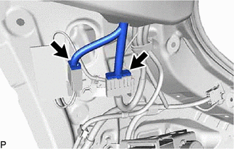
for Rear Pillar RH Side:
-
Disconnect the 2 connectors.
-
-
for Roof Side (w/o Sliding Roof):
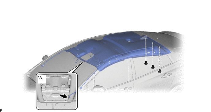
*A w/ Television Antenna - -
-
w/ Television Antenna:
-
Disconnect the connector.
-
-
Using a clip remover, remove the 3 clips.
-
-
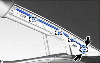
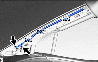
for Roof Side (w/ Sliding Roof):
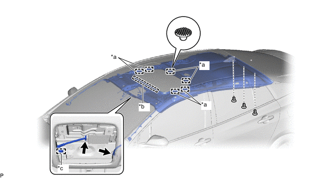
*a Fastener *b Guide *c Clamp - -
-
Using a clip remover, disengage the clamp.
-
Disconnect each connector.
-
Using a clip remover, remove the 3 clips.
-
Disengage the 6 fasteners and guide.
-
-
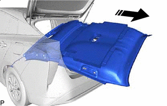
Remove in this Direction Remove the roof headlining assembly from the vehicle through the back door as shown in the illustration.
Note
Do not damage the roof headlining assembly or vehicle interior.
-