LOWER INSTRUMENT PANEL INSTALLATION
PROCEDURE
-
INSTALL LOWER INSTRUMENT PANEL SUB-ASSEMBLY
-
When installing a new lower instrument panel assembly, No. 1 instrument panel sub-assembly or lower instrument panel sub-assembly:
-
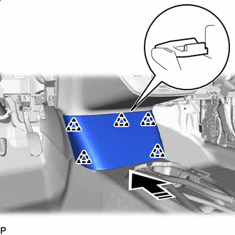
Immediately before installing the lower instrument panel assembly, twist and cut off the portion as shown in the illustration.
-
-
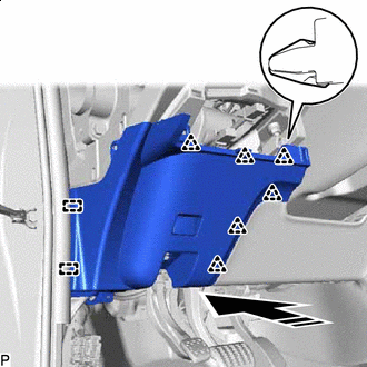
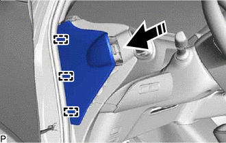
Install the lower instrument panel sub-assembly with the 2 bolts <A>, 4 bolts <B>, 3 screws <C> or <G> and screw <D>.
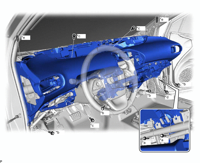
*a Bolt <A> *b Bolt <B> *c Screw <C> or <G> *d Screw <D> *e Clip - - Note
-
Do not damage the lower instrument panel sub-assembly.
-
Do not allow the wire harnesses to interfere with the surrounding parts.
-
If a screw <C> is loose and cannot be installed securely, replace it with a screw <G>.
- Torque:
- Bolt <A>
- 20 N*m { 204 kgf*cm, 15 ft.*lbf }
- Bolt <B>
- 13 N*m { 133 kgf*cm, 10 ft.*lbf }
-
-
Install the 2 clips.
-
Engage each clamp.
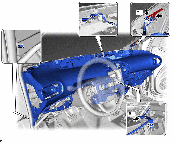
*A w/ Digital Audio Broadcasting Antenna or Television Antenna *B w/ Telematics Transceiver -
Connect each connector.
-
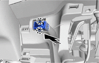

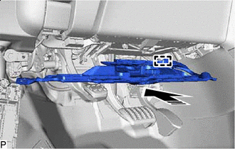
Install in this Direction Engage the 2 claws to connect the cooler (room temp. sensor) thermistor as shown in the illustration.
-
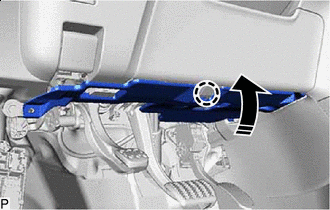
Engage the 4 clips and 2 claws to connect the lower instrument cover sub-assembly to the upper steering column cover.
-
-
CONNECT NO. 2 INSTRUMENT PANEL WIRE
-
INSTALL GLOVE BOX LIGHT ASSEMBLY
-
INSTALL NO. 2 INSTRUMENT PANEL REGISTER ASSEMBLY
-
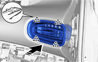
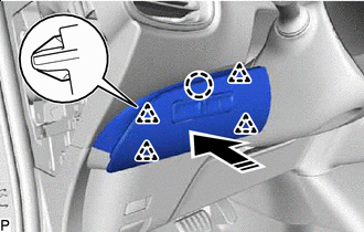
Install in this Direction Engage the 4 clips to install the No. 2 instrument panel register assembly as shown in the illustration.
-
-
INSTALL NO. 1 INSTRUMENT PANEL REGISTER ASSEMBLY
-
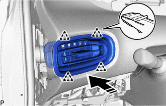
Install in this Direction Engage the 4 clips to install the No. 1 instrument panel register assembly as shown in the illustration.
-
-
INSTALL NO. 2 LOWER INSTRUMENT PANEL FINISH PANEL
-
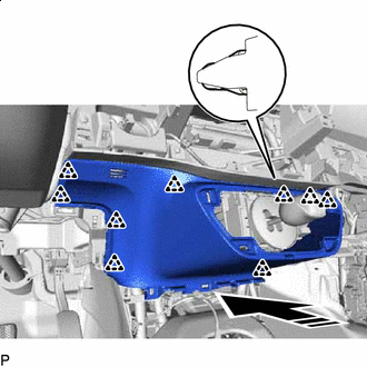
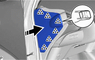
Install in this Direction Engage the 9 clips to install the No. 2 lower instrument panel finish panel as shown in the illustration.
-
-
INSTALL SHIFT LEVER HOLE COVER
-
Connect each connector
-
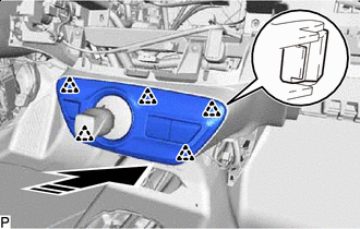
Install in this Direction Engage the 5 clips to install the shift lever hole cover as shown in the illustration.
-
Engage the clamp.
-
-
INSTALL LOWER CENTER INSTRUMENT CLUSTER FINISH PANEL SUB-ASSEMBLY
-
Connect each connector
-
Engage each clamp.
-
Install in this Direction Engage the 5 clips to install the lower center instrument cluster finish panel sub-assembly as shown in the illustration.
-
-
INSTALL GLOVE COMPARTMENT DOOR STOPPER SUB-ASSEMBLY
-
Engage the claw to install the glove compartment door stopper sub-assembly.
-
-
INSTALL GLOVE COMPARTMENT DOOR ASSEMBLY
-
Hold the glove compartment door assembly at an angle approximately 64.2° from its closed position and engage the 2 hinges horizontally as shown in the illustration.
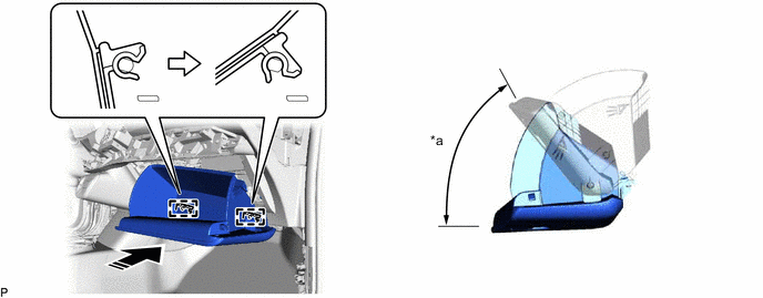
*a 64.2° - - Install in this Direction - - Note
Engaging the hinges from an upward angle will deform the hinges. Be sure to install the glove compartment door assembly horizontally.
-
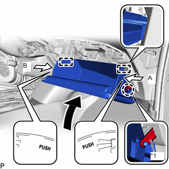
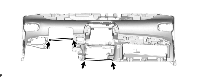
*1 Glove Compartment Door Stopper Sub-assembly Slightly bend the stoppers (A) and (B) in the directions indicated by the arrows shown in the illustration and engage the stoppers to install the glove compartment door assembly.
-
Engage the claw to connect the glove compartment door stopper sub-assembly.
-
-
INSTALL NO. 2 INSTRUMENT PANEL UNDER COVER SUB-ASSEMBLY
-
Connect the connector.
-
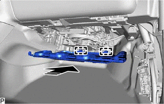
Install in this Direction Engage the 2 guides as shown in the illustration.
-
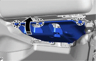
Install in this Direction Engage the 3 claws to install the No. 2 instrument panel under cover sub-assembly as shown in the illustration.
-
-
INSTALL COWL SIDE TRIM BOARD RH
-
INSTALL FRONT DOOR SCUFF PLATE RH
-
INSTALL RADIO TUNER OPENING COVER WITH BRACKET (w/o Radio Receiver)
-
Engage the clamp.
-
Engage the 2 guides.
-
Install the radio tuner opening cover with bracket with the 4 bolts <B>.
-
-
INSTALL RADIO RECEIVER ASSEMBLY WITH BRACKET (for Radio and Display Type)
-
INSTALL NAVIGATION RECEIVER ASSEMBLY WITH BRACKET (for Navigation Receiver Type)
-
INSTALL CENTER INSTRUMENT CLUSTER FINISH PANEL SUB-ASSEMBLY
-
Engage the clamp.
-
Connect each connector.
-
Engage the 5 guides and 18 clips to install the center instrument cluster finish panel sub-assembly as shown in the illustration.
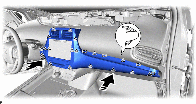
Install in this Direction - - -
for LHD:
-
Install the clip.
-
-
-
INSTALL INSTRUMENT PANEL FINISH PANEL END RH
-
w/ Airbag Cut Off Switch:
-
Connect the connector.
-
-
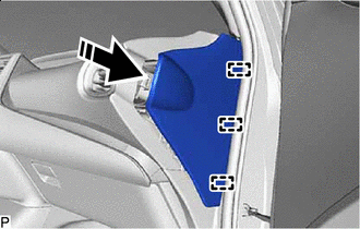
Install in this Direction Engage the 3 guides as shown in the illustration.
-
Install in this Direction Engage the 6 clips to install the instrument panel finish panel end RH as shown in the illustration.
-
-
INSTALL COMBINATION METER ASSEMBLY
-
INSTALL LOWER NO. 1 INSTRUMENT PANEL AIRBAG ASSEMBLY
-
INSTALL LOWER INSTRUMENT PANEL FINISH PANEL ASSEMBLY
-
Connect the connector.
-
Install in this Direction Engage the 2 guides and 6 clips as shown in the illustration.
-
Install the lower instrument panel finish panel assembly with the screw <C>.
-
-
CONNECT HOOD LOCK CONTROL LEVER SUB-ASSEMBLY
-
Engage the claw and 2 guides to connect the hood lock control lever sub-assembly.
-
-
INSTALL NO. 1 INSTRUMENT PANEL UNDER COVER SUB-ASSEMBLY
-
for RHD:
-
Engage the 2 claws to connect the DLC3 connector.
-
Engage the clamp.
-
-
Connect the connector.
-
Install in this Direction Engage the guide as shown in the illustration.
-
Install in this Direction Engage the claw as shown in the illustration.
-
Install the No. 1 instrument panel under cover sub-assembly with the 2 screws <F>.
-
-
INSTALL COWL SIDE TRIM BOARD LH
-
INSTALL FRONT DOOR SCUFF PLATE LH
-
INSTALL INSTRUMENT CLUSTER FINISH PANEL GARNISH ASSEMBLY
-
Connect each connector.
-
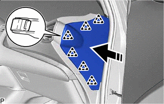
Install in this Direction Engage the claw and 4 clips to install the instrument cluster finish panel garnish assembly as shown in the illustration.
-
-
INSTALL INSTRUMENT PANEL FINISH PANEL END LH
-
Install in this Direction Engage the 3 guides as shown in the illustration.
-
Install in this Direction Engage the 6 clips to install the instrument panel finish panel end LH as shown in the illustration.
-
-
INSTALL REAR CONSOLE BOX ASSEMBLY
-
INSTALL UPPER INSTRUMENT PANEL ASSEMBLY
-
CONNECT CABLE TO NEGATIVE AUXILIARY BATTERY TERMINAL
Note
When disconnecting the cable, some systems need to be initialized after the cable is reconnected.
-
PERFORM DIAGNOSTIC SYSTEM CHECK
-
INSPECT SRS WARNING LIGHT