LOWER INSTRUMENT PANEL REMOVAL
CAUTION / NOTICE / HINT
The necessary procedures (adjustment, calibration, initialization or registration) that must be performed after parts are removed and installed, or replaced during lower instrument panel removal/installation are shown below.
| Replaced Part or Performed Procedure | Necessary Procedure | Effect/Inoperative Function when Necessary Procedure not Performed | Link |
|---|---|---|---|
| Disconnect cable from negative auxiliary battery terminal | Memorize steering angle neutral point | Lane departure alert system (w/ Steering Control) | |
| Intelligent clearance sonar system*1 | |||
| Simple intelligent parking assist system*1 | |||
| Pre-crash safety system | |||
| Parking assist monitor system | |||
| Initialize back door lock | Power door lock control system |
*1: When performing learning using the GTS.
PROCEDURE
-
PRECAUTION
CAUTION:
Some of these service operations affect the SRS airbag system. Read the precautionary notices concerning the SRS airbag system before servicing.
Note
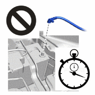
After turning the power switch off, waiting time may be required before disconnecting the cable from the negative (-) auxiliary battery terminal. Therefore, make sure to read the disconnecting the cable from the negative (-) auxiliary battery terminal notices before proceeding with work.
-
DISCONNECT CABLE FROM NEGATIVE AUXILIARY BATTERY TERMINAL
CAUTION:
Wait at least 90 seconds after disconnecting the cable from the negative (-) auxiliary battery terminal to disable the SRS system.
Note
When disconnecting the cable, some systems need to be initialized after the cable is reconnected.
-
REMOVE UPPER INSTRUMENT PANEL ASSEMBLY
-
REMOVE REAR CONSOLE BOX ASSEMBLY
-
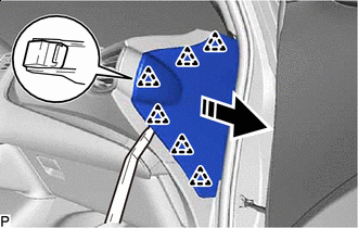
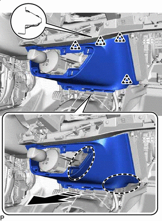
REMOVE INSTRUMENT PANEL FINISH PANEL END LH
-
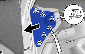

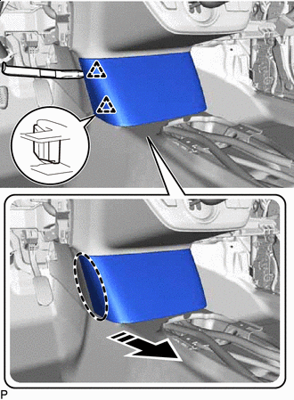
Remove in this Direction Using a moulding remover, disengage the 6 clips as shown in the illustration.
-
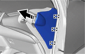
Remove in this Direction Disengage the 3 guides to remove the instrument panel finish panel end LH as shown in the illustration.
-
-
REMOVE INSTRUMENT CLUSTER FINISH PANEL GARNISH ASSEMBLY
-

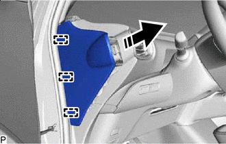
Place Hand Here Remove in this Direction Disengage the 4 clips and claw as shown in the illustration.
-
Disconnect each connector to remove the instrument cluster finish panel garnish assembly.
-
-
REMOVE FRONT DOOR SCUFF PLATE LH
-
REMOVE COWL SIDE TRIM BOARD LH
-
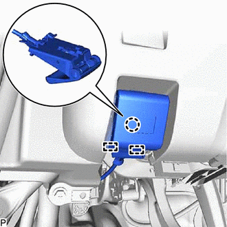
REMOVE NO. 1 INSTRUMENT PANEL UNDER COVER SUB-ASSEMBLY
-
Remove the 2 screws <F>.
-
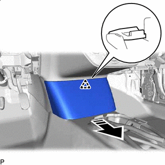
Remove in this Direction Disengage the claw as shown in the illustration.
-
Remove in this Direction Disengage the guide as shown in the illustration.
-
for LHD:
-
Disconnect the connector to remove the No. 1 instrument panel under cover sub-assembly.
-
-
for RHD:
-
Disconnect the connector.
-
Disengage the 2 claws to disconnect the DLC3 connector.
-
Disengage the clamp to remove the No. 1 instrument panel under cover sub-assembly.
-
-
-
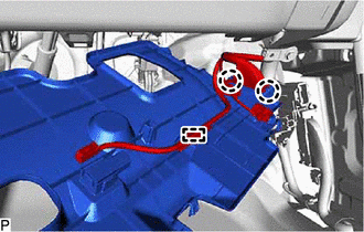
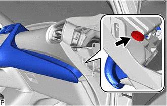
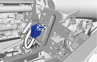
DISCONNECT HOOD LOCK CONTROL LEVER SUB-ASSEMBLY
-
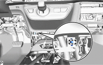
Disengage the claw and 2 guides to disconnect the hood lock control lever sub-assembly.
-
-
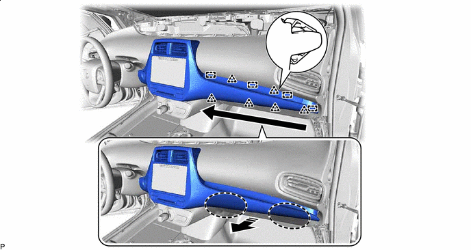
REMOVE LOWER INSTRUMENT PANEL FINISH PANEL ASSEMBLY
-
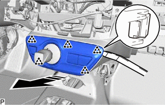
Remove the screw <C>.
-
Remove in this Direction Disengage the 6 clips and 2 guides as shown in the illustration.
-
Disconnect the connector to remove the lower instrument panel finish panel assembly.
-
-
REMOVE LOWER NO. 1 INSTRUMENT PANEL AIRBAG ASSEMBLY
-
REMOVE COMBINATION METER ASSEMBLY
-
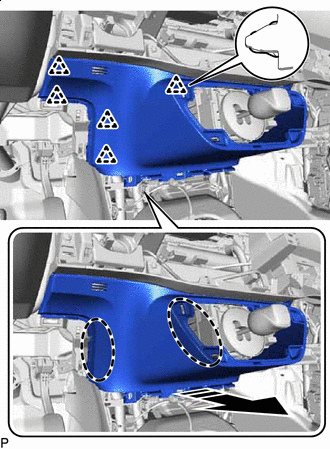
REMOVE INSTRUMENT PANEL FINISH PANEL END RH
-
Remove in this Direction Using a moulding remover, disengage the 6 clips as shown in the illustration.
-
Remove in this Direction Disengage the 3 guides as shown in the illustration.
-
w/ Airbag Cut Off Switch:
-
Disconnect the connector.
-
-
Remove the instrument panel finish panel end RH.
-
-
REMOVE CENTER INSTRUMENT CLUSTER FINISH PANEL SUB-ASSEMBLY
-
for LHD:
-
Remove the clip.
-
-
Disengage the 6 clips and 4 guides as shown in the illustration.
Place Hand Here Remove in this Direction 
Order of Removal - - -
Disengage the 12 clips and guide as shown in the illustration.
Place Hand Here Remove in this Direction -
Disconnect each connector.
-
Disengage the clamp to remove the center instrument cluster finish panel sub-assembly.
-
-
REMOVE RADIO TUNER OPENING COVER WITH BRACKET (w/o Radio Receiver)
-
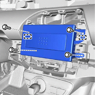
Remove the 4 bolts <B>.
-
Disengage the 2 guides.
-
Disengage the clamp to remove the radio tuner opening cover with bracket.
-
-
REMOVE RADIO RECEIVER ASSEMBLY WITH BRACKET (for Radio and Display Type)
-
REMOVE NAVIGATION RECEIVER ASSEMBLY WITH BRACKET (for Navigation Receiver Type)
-
REMOVE FRONT DOOR SCUFF PLATE RH
Tech Tips
Use the same procedure as for the LH side.
-
REMOVE COWL SIDE TRIM BOARD RH
Tech Tips
Use the same procedure as for the LH side.
-
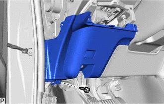
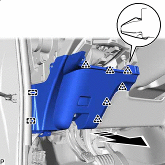
REMOVE NO. 2 INSTRUMENT PANEL UNDER COVER SUB-ASSEMBLY
-
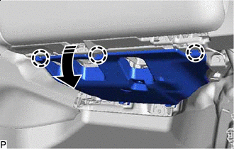
Remove in this Direction Disengage the 3 claws as shown in the illustration.
-
Remove in this Direction Disengage the 2 guides as shown in the illustration.
-
Disconnect the connector to remove the No. 2 instrument panel under cover sub-assembly.
-
-
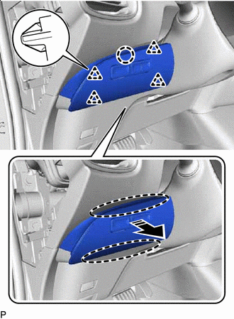
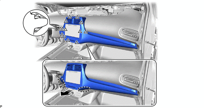
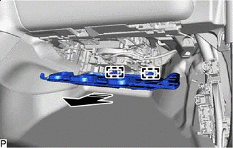
REMOVE GLOVE COMPARTMENT DOOR ASSEMBLY
-
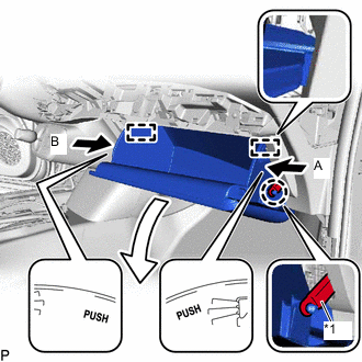
*1 Glove Compartment Door Stopper Sub-assembly Disengage the claw to disconnect the glove compartment door stopper sub-assembly.
-
Slightly bend stoppers (A) and (B) in the directions indicated by the arrows shown in the illustration and open the glove compartment door assembly until the stoppers are released.
-
Open the glove compartment door assembly to approximately 64.2° from its closed position. Pull it horizontally in the direction indicated by the arrow shown in the illustration to disengage the 2 hinges and remove the glove compartment door assembly.
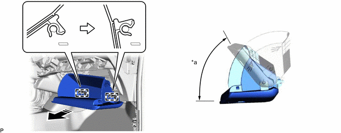
*a 64.2° - - Remove in this Direction - - Note
Pulling the glove compartment door assembly upward when removing it will cause the hinges to deform. Be sure to pull out the glove compartment door assembly horizontally.
-
-
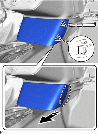
REMOVE GLOVE COMPARTMENT DOOR STOPPER SUB-ASSEMBLY
-

Disengage the claw to remove the glove compartment door stopper sub-assembly.
-
-
REMOVE LOWER CENTER INSTRUMENT CLUSTER FINISH PANEL SUB-ASSEMBLY
-
Insert Moulding Remover Here Remove in this Direction Using a moulding remover, disengage the 2 clips as shown in the illustration.
-
Insert Moulding Remover Here Remove in this Direction Using a moulding remover, disengage the 2 clips as shown in the illustration.
-
Remove in this Direction Disengage the clip as shown in the illustration.
-
Disconnect each connector.
-
Disengage each clamp to remove the lower center instrument cluster finish panel sub-assembly.
-
-
REMOVE SHIFT LEVER HOLE COVER
-
Disengage the clamp.
-
Remove in this Direction Using a moulding remover, disengage the 5 clips as shown in the illustration.
-
Disconnect each connector to remove the shift lever hole cover.
-
-
REMOVE NO. 2 LOWER INSTRUMENT PANEL FINISH PANEL
-
Place Hand Here Remove in this Direction Disengage the 4 clips as shown in the illustration.
-
Place Hand Here Remove in this Direction Disengage the 5 clips to remove the No. 2 lower instrument panel finish panel as shown in the illustration.
-
-
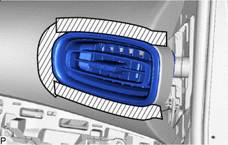
REMOVE NO. 1 INSTRUMENT PANEL REGISTER ASSEMBLY
-
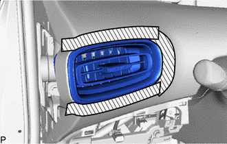

Protective Tape Apply protective tape to the areas shown in the illustration.
-
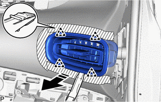
Remove in this Direction Using a moulding remover, disengage the 4 clips to remove the No. 1 instrument panel register assembly as shown in the illustration.
-
-
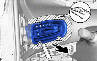
REMOVE NO. 2 INSTRUMENT PANEL REGISTER ASSEMBLY
-
Protective Tape Apply protective tape to the areas shown in the illustration.
-
Remove in this Direction Using a moulding remover, disengage the 4 clips to remove the No. 2 instrument panel register assembly as shown in the illustration.
-
-
REMOVE GLOVE BOX LIGHT ASSEMBLY
-
DISCONNECT NO. 2 INSTRUMENT PANEL WIRE
-
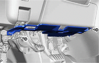
REMOVE LOWER INSTRUMENT PANEL SUB-ASSEMBLY
-
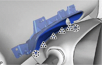
Disengage the 2 claws and 4 clips to disconnect the lower instrument cover sub-assembly from the upper steering column cover.
-
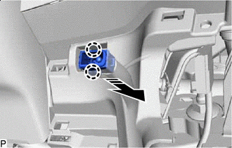
Remove in this Direction Disengage the 2 claws to disconnect the cooler (room temp. sensor) thermistor as shown in the illustration.
-
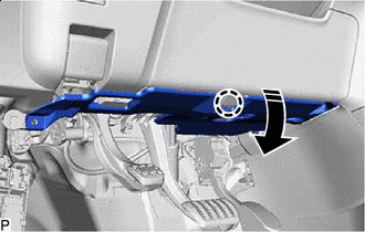
Disconnect each connector.
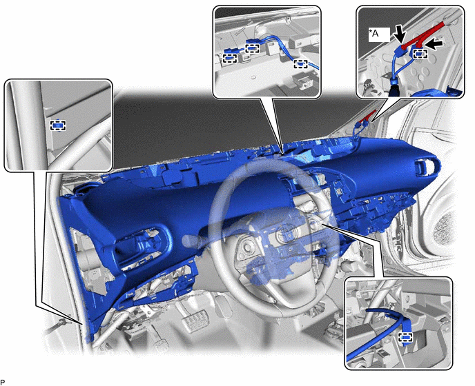
*A w/ Digital Audio Broadcasting Antenna or Television Antenna - - -
Disengage each clamp.
-
Remove the 2 clips.
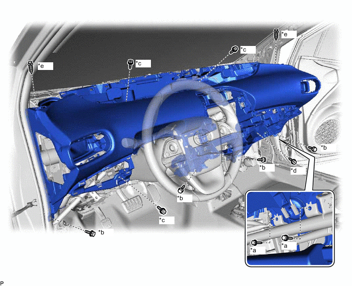
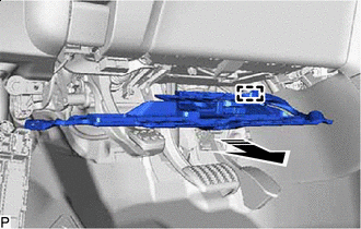
*a Bolt <A> *b Bolt <B> *c Screw <C> or <G> *d Screw <D> *e Clip - - -
Remove the 2 bolts <A>, 4 bolts <B>, 3 screws <C> or <G> and screw <D> and remove the lower instrument panel sub-assembly.
Note
-
Do not damage the lower instrument panel sub-assembly.
-
Do not allow the wire harnesses to interfere with the surrounding parts.
-
-