AIR CONDITIONING UNIT REASSEMBLY
PROCEDURE
-
INSTALL NO. 1 COOLER THERMISTOR
-
INSTALL NO. 1 COOLER EVAPORATOR SUB-ASSEMBLY
-
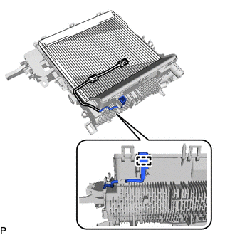
Install the No. 1 cooler evaporator sub-assembly with No. 1 cooler thermistor to the upper heater case.
-
Engage the clamp.
-
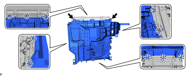
Engage the 10 claws to install the upper heater case with No. 1 cooler evaporator sub-assembly to the lower heater case.
-
Install the 2 screws.
-
-
INSTALL COOLER EXPANSION VALVE
-
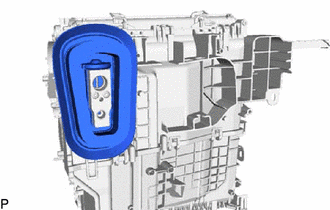
Sufficiently apply compressor oil to 2 new O-rings and the fitting surfaces of the No. 1 cooler evaporator sub-assembly.
Compressor Oil ND-OIL 11 or equivalent -
Install the 2 O-rings to the No. 1 cooler evaporator sub-assembly.
Note
Keep the O-rings and O-ring fitting surfaces free of foreign matter.
-
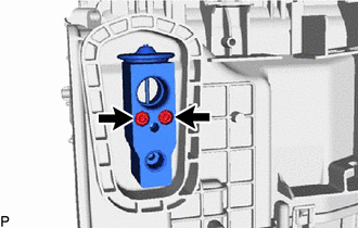
Using a 4 mm hexagon socket wrench, install the cooler expansion valve with the 2 hexagon bolts.
- Torque:
- 3.5 N*m { 36 kgf*cm, 31 in.*lbf }
-
Install the cooling unit parts.
-
-
INSTALL HEATER RADIATOR UNIT SUB-ASSEMBLY
-
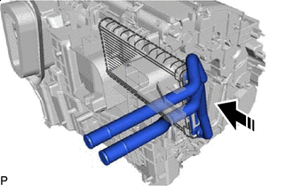

Install in this Direction Install the heater radiator unit sub-assembly as shown in the illustration.
-
-
INSTALL HEATER CLAMP
-
Engage the 4 claws to install the heater clamp.
-
-
INSTALL HEATER GROMMET
-
Install the heater grommet.
-
-
INSTALL NO. 3 AIR CONDITIONING RADIATOR DAMPER SERVO SUB-ASSEMBLY
-
for LHD:
-
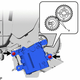
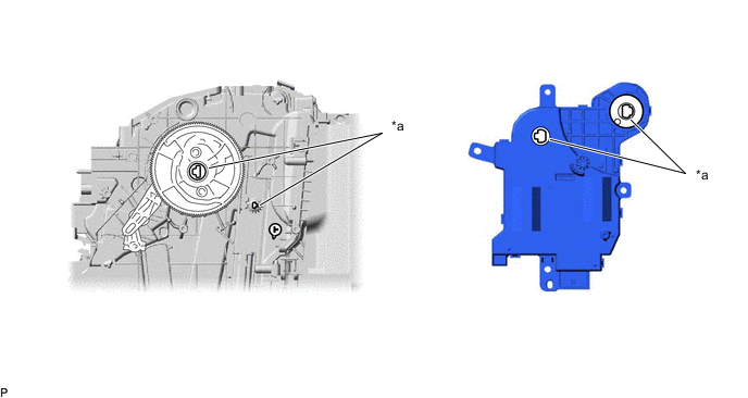
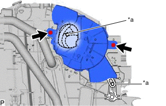
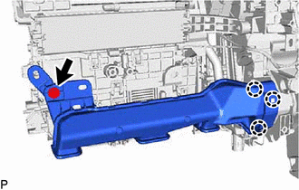
*a Reference Point Using the reference points, install the No. 3 air conditioning radiator damper servo sub-assembly with the 2 screws.
-
-
for RHD:
-
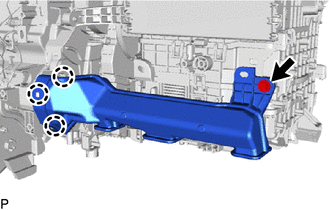
*a Reference Point Using the reference points, install the No. 3 air conditioning radiator damper servo sub-assembly with the 2 screws.
-
-
-
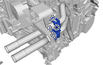
INSTALL NO. 2 AIR CONDITIONING RADIATOR DAMPER SERVO SUB-ASSEMBLY
-
for Single Air Conditioning System:
-
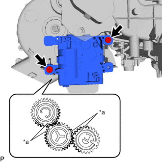
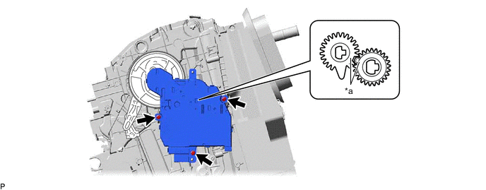
Align each gear on the air conditioner radiator assembly as shown in the illustration, and then check that the gears of the No. 2 air conditioning radiator damper servo sub-assembly are aligned as shown in the illustration.
*a Reference Point - - -
Install the No. 2 air conditioning radiator damper servo sub-assembly with the 3 screws.
-
-
for Dual Air Conditioning System:
-
Align each gear on the air conditioner radiator assembly as shown in the illustration, and then check that the gears of the No. 2 air conditioning radiator damper servo sub-assembly are aligned as shown in the illustration.
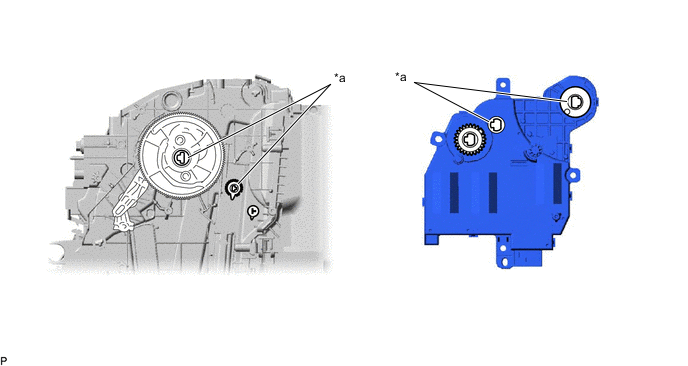
*a Reference Point - - -
Using the reference points, install the No. 2 air conditioning radiator damper servo sub-assembly with the 3 screws.
*a Reference Point - -
-
-
-
INSTALL NO. 1 AIR CONDITIONING RADIATOR DAMPER SERVO SUB-ASSEMBLY
-
for LHD:
-
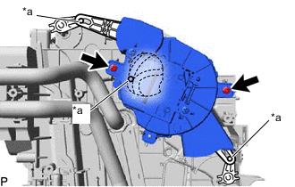
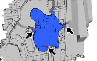
*a Link Connect the 3 links of the No. 1 air conditioning radiator damper servo sub-assembly to the 3 links of the air conditioning radiator assembly as shown in the illustration.
-
Install the No. 1 air conditioning radiator damper servo sub-assembly with the 2 screws.
-
-
for RHD:
-
*a Link Connect the 2 links of the No. 1 air conditioning radiator damper servo sub-assembly to the 2 links of the air conditioning radiator assembly as shown in the illustration.
-
Install the No. 1 air conditioning radiator damper servo sub-assembly with the 2 screws.
-
-
-
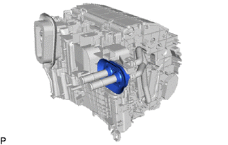
INSTALL DRAIN COOLER HOSE
-
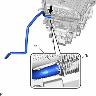
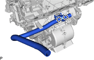
*a Hose Notch *b Rib Align the hose notch with the rib as shown in the illustration and install the drain cooler hose.
-
-
INSTALL AIR CONDITIONING HARNESS ASSEMBLY
-
for LHD:
-
Engage each clamp.
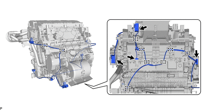
-
Connect each connector to install the air conditioning harness assembly.
-
-
for RHD:
-
Engage each clamp.
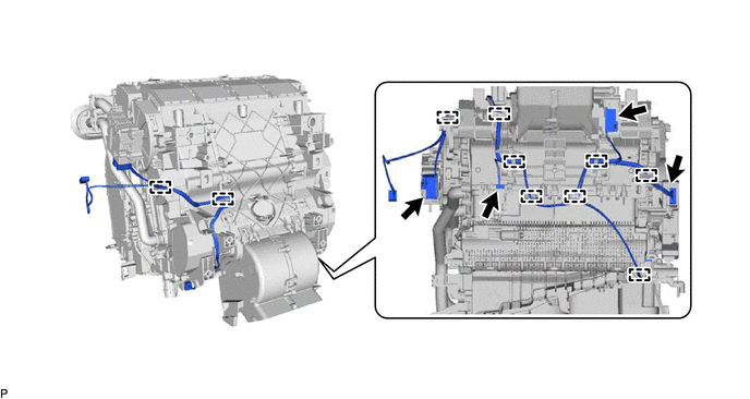
-
Connect each connector to install the air conditioning harness assembly.
-
-
-
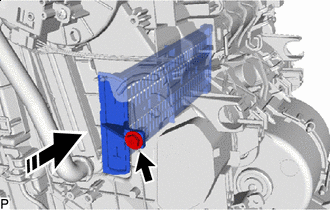
INSTALL AIR CONDITIONING AMPLIFIER ASSEMBLY
-
for LHD:
-
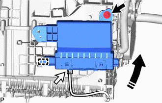
Install in this Direction Engage the guide to temporarily install the air conditioning amplifier assembly as shown in the illustration.
-
Install the air conditioning amplifier assembly with the screw.
-
Connect the connector.
-
-
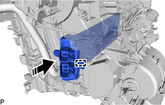
for RHD:
-
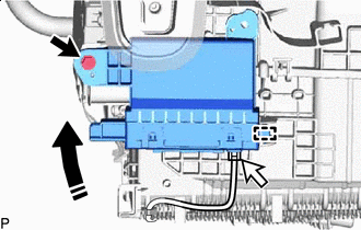
Install in this Direction Engage the guide to temporarily install the air conditioning amplifier assembly as shown in the illustration.
-
Install the air conditioning amplifier assembly with the screw.
-
Connect the connector.
-
-
-
INSTALL HEATER COVER (w/o PTC Heater)
-
Install in this Direction Install the heater cover with the screw as shown in the illustration.
-
-
INSTALL QUICK HEATER ASSEMBLY (w/ PTC Heater)
-
Install in this Direction Engage the guide to install the quick heater assembly as shown in the illustration.
-
-
INSTALL NO. 2 HEATER COVER (w/ PTC Heater)
-
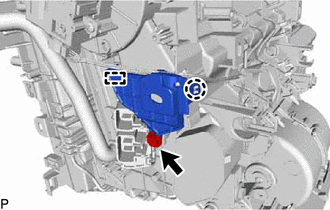
Engage the guide and claw.
-
Install the No. 2 heater cover with the screw.
-
-
INSTALL BLOWER ASSEMBLY
-
INSTALL NO. 3 INSTRUMENT PANEL WIRE (w/ PTC Heater)
-
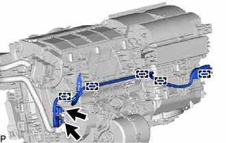
Engage the 5 clamps to install the No. 3 instrument panel wire.
-
Connect the 2 connectors.
-
-
INSTALL ASPIRATOR
-
Engage the 2 claws to install the aspirator.
-
-
INSTALL NO. 1 AIR DUCT (for RHD)
-
Engage the 3 claws.
-
Install a new No. 1 air duct with the screw.
-
-
INSTALL NO. 2 AIR DUCT (for LHD)
-
Engage the 3 claws.
-
Install a new No. 2 air duct with the screw.
-