AIR CONDITIONING UNIT REMOVAL
CAUTION / NOTICE / HINT
The necessary procedures (adjustment, calibration, initialization or registration) that must be performed after parts are removed and installed, or replaced during air conditioning unit removal/installation are shown below.
| Replaced Part or Performed Procedure | Necessary Procedure | Effect/Inoperative Function when Necessary Procedure not Performed | Link |
|---|---|---|---|
| Disconnect cable from negative auxiliary battery terminal | Memorize steering angle neutral point | Lane departure alert system (w/ Steering Control) | |
| Intelligent clearance sonar system*1 | |||
| Simple intelligent parking assist system*1 | |||
| Pre-crash safety system | |||
| Parking assist monitor system | |||
| Initialize back door lock | Power door lock control system | ||
|
Initialize servo motor (Air conditioning system) | DTCs are stored |
*1: When performing learning using the GTS.
PROCEDURE
-
PRECAUTION
Note
-
Make sure to select face mode before disconnecting the cable from the negative (-) auxiliary battery terminal.
-
Make sure to perform initialization after replacing the air conditioning radiator damper servo sub-assembly. If initialization is not performed, the air conditioner unit assembly will not perform properly as the air conditioning amplifier assembly will not be able to recognize the position of the air conditioning radiator damper sub-assembly.
-
-
RECOVER REFRIGERANT FROM REFRIGERATION SYSTEM
for HFC-134a (R134a):
for HFO-1234yf (R1234yf):
-
REMOVE WINDSHIELD WIPER MOTOR AND LINK ASSEMBLY
-
REMOVE NO. 1 HEATER AIR DUCT SPLASH SHIELD SEAL (for LHD)
-
REMOVE NO. 2 HEATER AIR DUCT SPLASH SHIELD SEAL (for RHD)
-
REMOVE WATER GUARD PLATE LH
-
REMOVE COWL BODY MOUNTING REINFORCEMENT LH
-
REMOVE OUTER COWL TOP PANEL SUB-ASSEMBLY
-
DISCONNECT OUTLET HEATER WATER HOSE A (w/o Exhaust Heat Recirculation System)
-
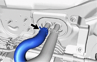
Using pliers, grip the claws of the clip and slide the clip to disconnect the outlet heater water hose A.
Note
-
Do not apply excessive force to the outlet heater water hose A.
-
Prepare a drain pan or cloth in case the coolant leaks.
-
-
-
DISCONNECT WATER PIPE AND HOSE SUB-ASSEMBLY A (w/ Exhaust Heat Recirculation System)
-
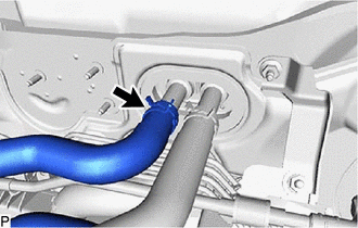
Using pliers, grip the claws of the clip and slide the clip to disconnect the water pipe and hose sub-assembly A.
Note
-
Do not apply excessive force to the water pipe and hose sub-assembly A.
-
Prepare a drain pan or cloth in case the coolant leaks.
-
-
-
DISCONNECT INLET HEATER WATER HOSE A
-
w/o Exhaust Heat Recirculation System:
-
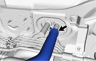
Using pliers, grip the claws of the clip and slide the clip to disconnect the inlet heater water hose A.
Note
-
Do not apply excessive force to the inlet heater water hose A.
-
Prepare a drain pan or cloth in case the coolant leaks.
-
-
-
w/ Exhaust Heat Recirculation System:
-
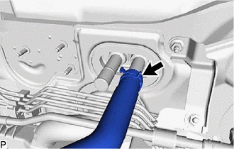
Using pliers, grip the claws of the clip and slide the clip to disconnect the inlet heater water hose A.
Note
-
Do not apply excessive force to the inlet heater water hose A.
-
Prepare a drain pan or cloth in case the coolant leaks.
-
-
-
-
DISCONNECT SUCTION PIPE SUB-ASSEMBLY
-
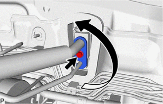
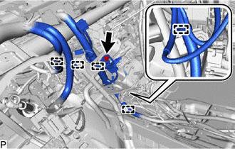
Remove the bolt and rotate the hook connector as shown in the illustration.
-
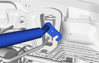
Disconnect the suction pipe sub-assembly.
-
Remove the O-ring from the suction pipe sub-assembly.
Note
Seal the openings of the disconnected parts using vinyl tape to prevent entry of moisture and foreign matter.
-
-
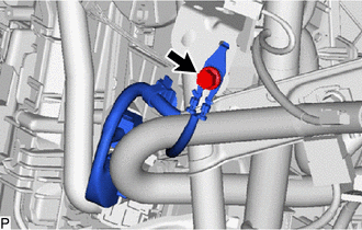
DISCONNECT AIR CONDITIONER TUBE AND ACCESSORY ASSEMBLY
-
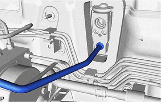
Disconnect the air conditioner tube and accessory assembly.
-
Remove the O-ring from the air conditioner tube and accessory assembly.
Note
Seal the openings of the disconnected parts using vinyl tape to prevent entry of moisture and foreign matter.
-
-
REMOVE FRONT SEAT ASSEMBLY LH
for Manual seat:
for Power seat:
-
REMOVE FRONT SEAT ASSEMBLY RH
-
REMOVE LOWER INSTRUMENT PANEL SUB-ASSEMBLY
-
REMOVE STEERING COLUMN ASSEMBLY
-
REMOVE SKID CONTROL BUZZER (w/ Toyota Safety Sense P)
-
REMOVE DRIVING SUPPORT ECU ASSEMBLY (w/ Toyota Safety Sense P)
-
REMOVE WINDSHIELD WIPER RELAY ASSEMBLY (w/ Rain Sensor)
-
REMOVE NO. 1 CLEARANCE WARNING BUZZER (w/ TOYOTA Parking Assist-sensor System)
-
REMOVE NO. 2 CLEARANCE WARNING BUZZER (w/ TOYOTA Parking Assist-sensor System)
-
REMOVE CLEARANCE WARNING ECU ASSEMBLY (w/ TOYOTA Parking Assist-sensor System)
-
REMOVE DOUBLE LOCK DOOR CONTROL RELAY ASSEMBLY (w/ Double Locking System)
-
REMOVE ECU INTEGRATION BOX RH (for LHD)
-
REMOVE ECU INTEGRATION BOX LH (for RHD)
-
REMOVE TELEMATICS TRANSCEIVER WITH ANTENNA CORD (w/ Telematics Transceiver)
-
REMOVE SHIFT LOCK CONTROL UNIT ASSEMBLY
-
REMOVE COOLER (ROOM TEMP. SENSOR) THERMISTOR
-
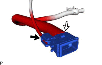
Disconnect the connector and aspirator to remove the cooler (room temp. sensor) thermistor.
-
-
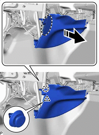
REMOVE FRONT NO. 1 CONSOLE BOX INSERT
-
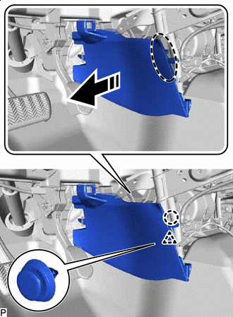

Place Hand Here 
Remove in this Direction Disengage the clip and claw as shown in the illustration.
-
Remove in this Direction Disengage the guide to remove the front No. 1 console box insert as shown in the illustration.
-
-
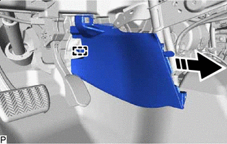
REMOVE FRONT NO. 2 CONSOLE BOX INSERT
-
Place Hand Here Remove in this Direction Disengage the clip and claw as shown in the illustration.
-
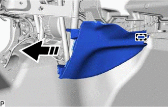
Remove in this Direction Disengage the guide to remove the front No. 2 console box insert as shown in the illustration.
-
-
REMOVE FRONT FLOOR CAUTION PLATE COVER
-
Place Hand Here Remove in this Direction (1) 
Remove in this Direction (2) Disengage the claw and guide as shown by the arrow (1), and then pull the front floor caution plate cover as shown by the arrow (2) in the illustration to remove it.
-
-
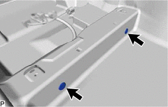
REMOVE REAR NO. 3 AIR DUCT
-
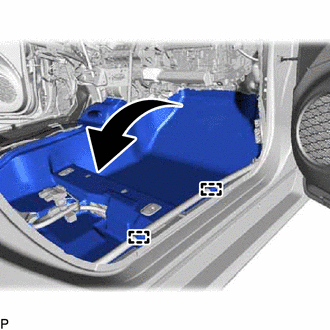
Remove the 2 front floor carpet clips.
-
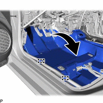
Disengage the 2 guides and turn back the front floor carpet assembly as shown in the illustration.
-
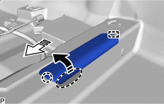
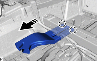
Remove in this Direction Disengage the 2 claws to remove the rear No. 3 air duct as shown in the illustration.
-
-
REMOVE REAR NO. 2 AIR DUCT
-
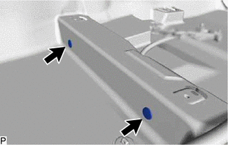
Disengage the 2 claws and remove the rear No. 2 air duct.
-
-
REMOVE REAR NO. 5 AIR DUCT
-
Remove the 2 front floor carpet clips.
-
Disengage the 2 guides and turn back the front floor carpet assembly as shown in the illustration.
-
Remove in this Direction Disengage the 2 claws to remove the rear No. 5 air duct as shown in the illustration.
-
-
REMOVE REAR NO. 4 AIR DUCT
-
Disengage the 2 claws and remove the rear No. 4 air duct.
-
-
REMOVE REAR NO. 1 AIR DUCT
-
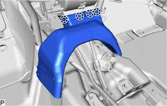
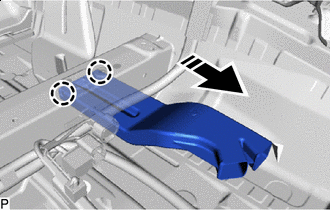
Disengage the 4 claws to remove the rear No. 1 air duct.
-
-
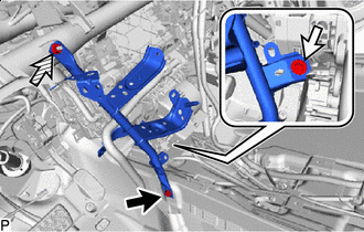
REMOVE NO. 3 DASH PANEL INSULATOR PAD
-
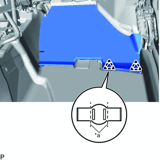
*a Cut Cut each claw of the 2 clips and remove the No. 3 dash panel insulator pad.
Note
If the No. 3 dash panel insulator pad is damaged, replace it with a new one.
-
Remove the 2 clips.
-
-
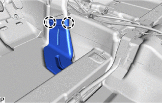
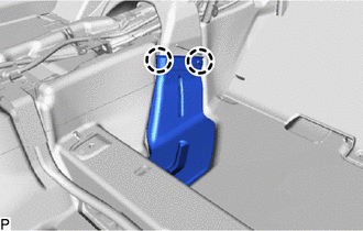
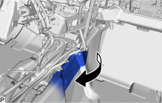
REMOVE NO. 1 INSTRUMENT PANEL BRACE SUB-ASSEMBLY
-
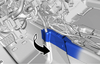
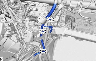
Turn back the front floor mat as shown in the illustration.
-
Disengage each clamp.
-
Remove the bolt and disconnect the earth wire.
-
w/ PTC Heater:
-
Remove the bolt and disconnect the earth wire.
-
-

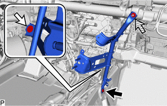
Bolt 
Screw 
Nut Remove the bolt, screw, nut and No. 1 instrument panel brace sub-assembly.
-
-
REMOVE NO. 2 INSTRUMENT PANEL BRACE SUB-ASSEMBLY
-
Turn back the front floor mat as shown in the illustration.
-
Disengage each clamp.
-
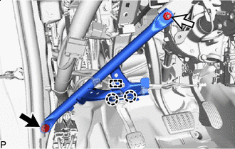
Bolt Screw Nut Remove the bolt, screw, nut and No. 2 instrument panel brace sub-assembly.
-
-
REMOVE NO. 3 INSTRUMENT PANEL TO COWL BRACE SUB-ASSEMBLY
-
for LHD:
-
Bolt Nut Disengage the clamp and 2 claws to disconnect the DLC3 connector.
-
-
Remove the bolt, nut and No. 3 instrument panel to cowl brace sub-assembly.
-
-
REMOVE INSTRUMENT PANEL JUNCTION BLOCK ASSEMBLY WITH MAIN BODY ECU
-
REMOVE LOWER DEFROSTER NOZZLE ASSEMBLY
-
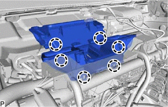
Disengage the 6 claws to remove the lower defroster nozzle assembly.
-
-
REMOVE INSTRUMENT PANEL REINFORCEMENT ASSEMBLY WITH AIR CONDITIONER UNIT ASSEMBLY
Note
-
Be sure to support the air conditioner unit assembly when removing it. Failure to do so may cause the bracket of the air conditioner unit assembly to break.
-
When disassembling the air conditioner unit assembly, eliminate static electricity by touching the vehicle body to prevent the components from being damaged.
-
for LHD:
-
Disconnect each connector.
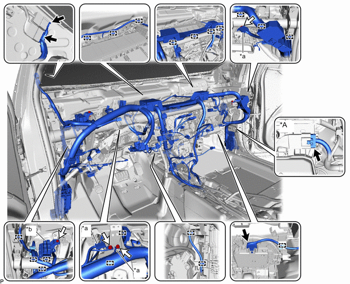
*A w/ PTC Heater - - *a Earth Wire *b Relay Block Assembly Connector Bolt -
Remove the 3 bolts and disconnect the 3 earth wires.
-
Remove the bolt and disconnect the relay block assembly.
-
Disengage each clamp and disconnect the instrument panel wire.
-
-
for RHD:
-
Disconnect each connector.
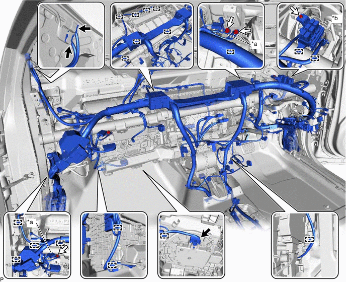
*a Earth Wire *b Relay Block Assembly Connector Bolt -
Remove the 3 bolts and disconnect the 3 earth wires.
-
Remove the bolt and disconnect the relay block assembly.
-
Disengage each clamp and disconnect the instrument panel wire.
-
-
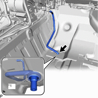
*1 COOLER UNIT DRAIN HOSE GROMMET Disconnect the drain cooler hose.
Note
If the cooler unit drain hose grommet is disconnected from the vehicle body while disconnecting the drain cooler hose, make sure to replace it with a new one. Failure to do so may cause water ingress.
-
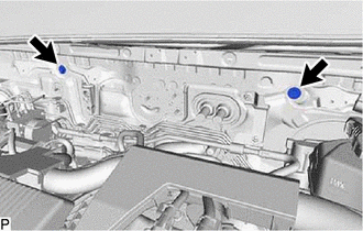
Remove the 2 bolts.
-
Remove the 4 bolts (A).
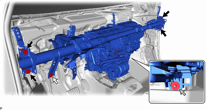
Bolt (A) Bolt (B) Nut - - -
Remove the bolt (B) and disconnect the parking brake pedal assembly.
-
Remove the nut.
-
Disconnect each connector.
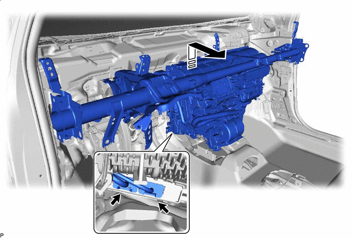
Remove in this Direction - - -
Remove the instrument panel reinforcement assembly with air conditioner unit assembly as shown in the illustration.
-
-
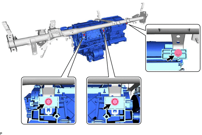
REMOVE AIR CONDITIONER UNIT ASSEMBLY
-
Remove the 3 bolts and air conditioner unit assembly from the instrument panel reinforcement assembly.
-