LUMBAR SUPPORT ADJUSTER ASSEMBLY(for Manual Seat) REMOVAL
CAUTION / NOTICE / HINT
The necessary procedures (adjustment, calibration, initialization, or registration) that must be performed after parts are removed, installed, or replaced during the lumbar support adjuster assembly removal/installation are shown below.
| Replacement Part or Procedure | Necessary Procedures | Effects / Inoperative when not performed | Link |
|---|---|---|---|
| Disconnect cable from negative auxiliary battery terminal | Memorize steering angle neutral point | Lane departure alert system (w/ Steering Control) | |
| Intelligent clearance sonar system | |||
| Simple intelligent parking assist system | |||
| Pre-crash safety system | |||
| Parking assist monitor system | |||
| Initialize back door lock | Power door lock control system |
CAUTION:
-
Be sure to read Precaution thoroughly before servicing.
-
Wear protective gloves. Sharp areas on the parts may injure your hands.
Tech Tips
-
Lumbar support adjuster assembly is available only on the driver side.
-
Use the same procedure for RHD and LHD vehicles.
-
The following procedure is for LHD vehicles.
PROCEDURE
-
REMOVE FRONT SEAT ASSEMBLY LH
-
DISCONNECT SEPARATE TYPE FRONT SEATBACK COVER
-
REMOVE VERTICAL ADJUSTING HANDLE LH
-
REMOVE NO. 1 RECLINING HINGE COVER
-
REMOVE RECLINING ADJUSTER RELEASE HANDLE LH
-
REMOVE SEAT ADJUSTER COVER CAP LH
-
REMOVE FRONT SEAT CUSHION SHIELD LH
-
REMOVE FRONT SEAT INNER CUSHION SHIELD LH
-
REMOVE SEPARATE TYPE FRONT SEATBACK ASSEMBLY
-
REMOVE FRONT SEAT HEADREST SUPPORT
-
REMOVE SEPARATE TYPE FRONT SEATBACK COVER WITH PAD
-
REMOVE LUMBAR SUPPORT ADJUSTER ASSEMBLY LH
-
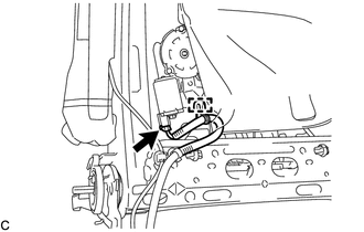
Disconnect the lumbar support adjuster assembly connector.
-
Disengage the clamp.
-
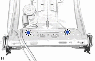
Disengage the 2 claws to remove the 2 front seatback edge protectors from the front seatback frame sub-assembly.
-
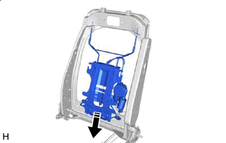

Remove in this direction Remove the lumbar support adjuster assembly from the front seatback frame sub-assembly as shown in the illustration.
-
-
REMOVE FRONT SEATBACK EDGE PROTECTOR