AIRBAG SYSTEM, Diagnostic DTC:B1805/52, B1806/52, B1807/52, B1808/52

| DTC Code | DTC Name |
|---|---|
| B1805/52 | Short in Front Passenger Side Squib Circuit |
| B1806/52 | Open in Front Passenger Side Squib Circuit |
| B1807/52 | Short to GND in Front Passenger Side Squib Circuit |
| B1808/52 | Short to B+ in Front Passenger Side Squib Circuit |
DESCRIPTION
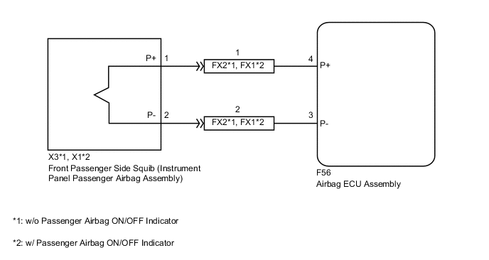
The front passenger side squib circuit consists of the airbag ECU assembly and instrument panel passenger airbag assembly.
The airbag ECU assembly uses this circuit to deploy the airbag when deployment conditions are met.
These DTCs are stored when a malfunction is detected in the front passenger side squib circuit.
| DTC No. | Detection Item | DTC Detection Condition | Trouble Area | Test Mode / Check Mode |
|---|---|---|---|---|
| B1805/52 | Short in Front Passenger Side Squib Circuit |
|
|
Applies to check mode |
| B1806/52 | Open in Front Passenger Side Squib Circuit |
|
|
Applies to check mode |
| B1807/52 | Short to GND in Front Passenger Side Squib Circuit |
|
|
Applies to check mode |
| B1808/52 | Short to B+ in Front Passenger Side Squib Circuit |
|
|
Applies to check mode |
WIRING DIAGRAM
CAUTION / NOTICE / HINT
Note
After turning the power switch off, waiting time may be required before disconnecting the cable from the negative (-) auxiliary battery terminal. Therefore, make sure to read the disconnecting the cable from the negative (-) auxiliary battery terminal notices before proceeding with work.
Tech Tips
-
Perform the simulation method by selecting check mode (Signal Check) using the GTS.
-
After selecting check mode (Signal Check), perform the simulation method by wiggling each connector of the airbag system or driving the vehicle on a city road or rough road.
PROCEDURE
-
CHECK VEHICLE CONDITION
-
Choose the model to be inspected.
Result Result Proceed to w/o Passenger Airbag ON/OFF Indicator A w/ Passenger Airbag ON/OFF Indicator B
B 
CHECK CONNECTORS Click here
A 
-
-
CHECK CONNECTORS
-
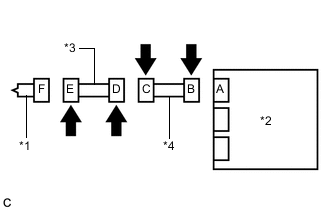
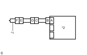
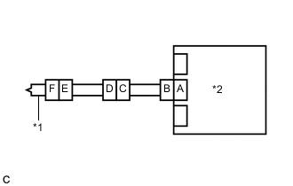
*1 Instrument Panel Passenger Airbag Assembly *2 Airbag ECU Assembly *3 No. 2 Instrument Panel Wire *4 Instrument Panel Wire Turn the power switch off.
-
Disconnect the cable from the negative (-) auxiliary battery terminal.
CAUTION:
Wait at least 90 seconds after disconnecting the cable from the negative (-) auxiliary battery terminal to disable the SRS system.
-
Check that the connectors are properly connected to the instrument panel passenger airbag assembly and airbag ECU assembly. Also check that the connectors that link the instrument panel wire and No. 2 instrument panel wire are properly connected.
OK The connectors are properly connected. Tech Tips
If the connectors are not properly connected, reconnect the connectors and proceed to the next inspection.
-
Disconnect the connectors from the instrument panel passenger airbag assembly and airbag ECU assembly. Also disconnect the instrument panel wire from the No. 2 instrument panel wire.
-
Check that the terminals of the connectors are not deformed or damaged.
OK The terminals are not deformed or damaged. -
Check that the No. 2 instrument panel wire connector (on the instrument panel passenger airbag assembly side) is not loose, deformed or damaged.
OK The connector locking button is not disengaged, and the claw of the lock is not deformed or damaged. -
Check that the short springs of the activation prevention mechanisms of the instrument panel wire connector and No. 2 instrument panel wire connector are not deformed or damaged.
OK The short springs are not deformed or damaged. Result Proceed to OK NG
NG 
REPLACE WIRE HARNESS
OK
-
-
CHECK INSTRUMENT PANEL PASSENGER AIRBAG ASSEMBLY
-
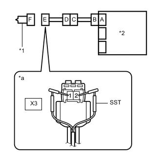
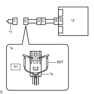
*1 Instrument Panel Passenger Airbag Assembly *2 Airbag ECU Assembly *a Front view of wire harness connector
(to Instrument Panel Passenger Airbag Assembly)
Connect the instrument panel wire to the No. 2 instrument panel wire and airbag ECU assembly.
-
Connect SST (resistance 2.1 Ω) to connector E.
CAUTION:
Never connect a tester to the instrument panel passenger airbag assembly for measurement, as this may lead to a serious injury due to airbag deployment.
Note
-
Do not forcibly insert SST into the terminals of the connector when connecting it.
-
Insert SST straight into the terminals of the connector.
- SST
- 09843-18061
-
-
Connect the cable to the negative (-) auxiliary battery terminal.
-
Clear the DTCs stored in memory.
Body Electrical > SRS Airbag > Clear DTCs -
Turn the power switch off.
-
Turn the power switch on (IG), and wait for at least 60 seconds.
-
Check for DTCs.
Body Electrical > SRS Airbag > Trouble CodesOK DTC B1805/52, B1806/52, B1807/52 or B1808/52 is not output. Tech Tips
Codes other than DTCs B1805/52, B1806/52, B1807/52 and B1808/52 may be output at this time, but they are not related to this check.
-
Turn the power switch off.
-
Disconnect the cable from the negative (-) auxiliary battery terminal.
CAUTION:
Wait at least 90 seconds after disconnecting the cable from the negative (-) auxiliary battery terminal to disable the SRS system.
-
Disconnect SST from connector E.
Result Proceed to OK NG
OK
REPLACE INSTRUMENT PANEL PASSENGER AIRBAG ASSEMBLY Click here
NG
-
-
CHECK FRONT PASSENGER SIDE SQUIB CIRCUIT
-
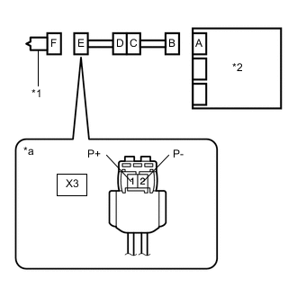
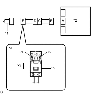
*1 Instrument Panel Passenger Airbag Assembly *2 Airbag ECU Assembly *a Front view of wire harness connector
(to Instrument Panel Passenger Airbag Assembly)
Disconnect the instrument panel wire from the airbag ECU assembly.
-
Check for a short to B+ in the circuit.
-
Connect the cable to the negative (-) auxiliary battery terminal.
-
Turn the power switch on (IG).
-
Measure the voltage according to the value(s) in the table below.
Standard Voltage Tester Connection Condition Specified Condition X3-1 (P+) - Body ground Power switch on (IG) Below 1 V X3-2 (P-) - Body ground Power switch on (IG) Below 1 V -
Turn the power switch off.
-
Disconnect the cable from the negative (-) auxiliary battery terminal.
CAUTION:
Wait at least 90 seconds after disconnecting the cable from the negative (-) auxiliary battery terminal to disable the SRS system.
-
-
Check for an open in the circuit.
-
Measure the resistance according to the value(s) in the table below.
Standard Resistance Tester Connection Condition Specified Condition X3-1 (P+) - X3-2 (P-) Always Below 1 Ω
-
-
Check for a short to ground in the circuit.
-
Measure the resistance according to the value(s) in the table below.
Standard Resistance Tester Connection Condition Specified Condition X3-1 (P+) - Body ground Always 1 MΩ or higher X3-2 (P-) - Body ground Always 1 MΩ or higher
-
-
Check for a short in the circuit.
-
Release the activation prevention mechanism built into connector B.
-
Measure the resistance according to the value(s) in the table below.
Standard Resistance Tester Connection Condition Specified Condition X3-1 (P+) - X3-2 (P-) Always 1 MΩ or higher -
Restore the released activation prevention mechanism of connector B to the original condition.
Result Proceed to OK NG -
NG
CHECK INSTRUMENT PANEL WIRE Click here
OK
-
-
CHECK DTC
-
*1 Instrument Panel Passenger Airbag Assembly *2 Airbag ECU Assembly Connect the connectors to the instrument panel passenger airbag assembly and airbag ECU assembly.
-
Connect the cable to the negative (-) auxiliary battery terminal.
-
Clear the DTCs stored in memory.
Body Electrical > SRS Airbag > Clear DTCs -
Turn the power switch off.
-
Turn the power switch on (IG), and wait for at least 60 seconds.
-
Check for DTCs.
Body Electrical > SRS Airbag > Trouble CodesOK DTC B1805/52, B1806/52, B1807/52 or B1808/52 is not output. Tech Tips
Codes other than DTCs B1805/52, B1806/52, B1807/52 and B1808/52 may be output at this time, but they are not related to this check.
Result Proceed to OK NG
OK
USE SIMULATION METHOD TO CHECK Click here
NG
REPLACE AIRBAG ECU ASSEMBLY Click here
-
-
CHECK INSTRUMENT PANEL WIRE
-
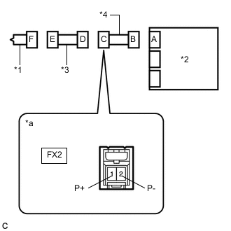
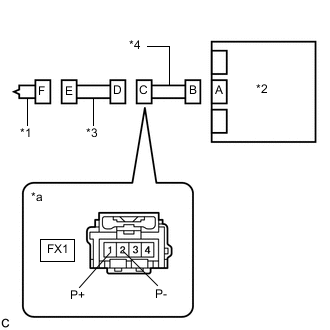
*1 Instrument Panel Passenger Airbag Assembly *2 Airbag ECU Assembly *3 No. 2 Instrument Panel Wire *4 Instrument Panel Wire *a Front view of wire harness connector
(to No. 2 Instrument Panel Wire)
Disconnect the No. 2 instrument panel wire from the instrument panel wire.
-
Check for a short to B+ in the circuit.
-
Connect the cable to the negative (-) auxiliary battery terminal.
-
Turn the power switch on (IG).
-
Measure the voltage according to the value(s) in the table below.
Standard Voltage Tester Connection Condition Specified Condition FX2 -1 (P+) - Body ground Power switch on (IG) Below 1 V FX2 -2 (P-) - Body ground Power switch on (IG) Below 1 V -
Turn the power switch off.
-
Disconnect the cable from the negative (-) auxiliary battery terminal.
CAUTION:
Wait at least 90 seconds after disconnecting the cable from the negative (-) auxiliary battery terminal to disable the SRS system.
-
-
Check for an open in the circuit.
-
Measure the resistance according to the value(s) in the table below.
Standard Resistance Tester Connection Condition Specified Condition FX2 -1 (P+) - FX2 -2 (P-) Always Below 1 Ω
-
-
Check for a short to ground in the circuit.
-
Measure the resistance according to the value(s) in the table below.
Standard Resistance Tester Connection Condition Specified Condition FX2 -1 (P+) - Body ground Always 1 MΩ or higher FX2 -2 (P-) - Body ground Always 1 MΩ or higher
-
-
Check for a short in the circuit.
-
Release the activation prevention mechanism built into connector B.
-
Measure the resistance according to the value(s) in the table below.
Standard Resistance Tester Connection Condition Specified Condition FX2 -1 (P+) - FX2 -2 (P-) Always 1 MΩ or higher -
Restore the released activation prevention mechanism of connector B to the original condition.
Result Proceed to OK NG -
NG
REPLACE INSTRUMENT PANEL WIRE
OK
-
-
CHECK NO. 2 INSTRUMENT PANEL WIRE
-
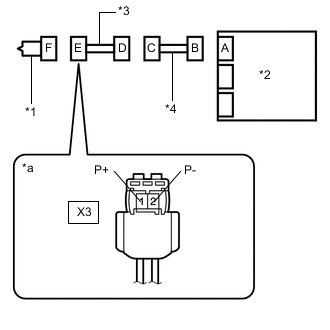
*1 Instrument Panel Passenger Airbag Assembly *2 Airbag ECU Assembly *3 No. 2 Instrument Panel Wire *4 Instrument Panel Wire *a Front view of wire harness connector
(to Instrument Panel Passenger Airbag Assembly)
Check for a short to B+ in the circuit.
-
Connect the cable to the negative (-) auxiliary battery terminal.
-
Turn the power switch on (IG).
-
Measure the voltage according to the value(s) in the table below.
Standard Voltage Tester Connection Condition Specified Condition X3-1 (P+) - Body ground Power switch on (IG) Below 1 V X3-2 (P-) - Body ground Power switch on (IG) Below 1 V -
Turn the power switch off.
-
Disconnect the cable from the negative (-) auxiliary battery terminal.
CAUTION:
Wait at least 90 seconds after disconnecting the cable from the negative (-) auxiliary battery terminal to disable the SRS system.
-
-
Check for an open in the circuit.
-
Measure the resistance according to the value(s) in the table below.
Standard Resistance Tester Connection Condition Specified Condition X3-1 (P+) - X3-2 (P-) Always Below 1 Ω
-
-
Check for a short to ground in the circuit.
-
Measure the resistance according to the value(s) in the table below.
Standard Resistance Tester Connection Condition Specified Condition X3-1 (P+) - Body ground Always 1 MΩ or higher X3-2 (P-) - Body ground Always 1 MΩ or higher
-
-
Check for a short in the circuit.
-
Release the activation prevention mechanism built into connector D.
-
Measure the resistance according to the value(s) in the table below.
Standard Resistance Tester Connection Condition Specified Condition X3-1 (P+) - X3-2 (P-) Always 1 MΩ or higher -
Restore the released activation prevention mechanism of connector D to the original condition.
Result Proceed to OK NG -
OK
USE SIMULATION METHOD TO CHECK Click here
NG
REPLACE NO. 2 INSTRUMENT PANEL WIRE
-
-
CHECK CONNECTORS
-
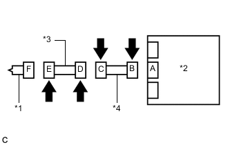
*1 Instrument Panel Passenger Airbag Assembly *2 Airbag ECU Assembly *3 No. 2 Instrument Panel Wire *4 Instrument Panel Wire Turn the power switch off.
-
Disconnect the cable from the negative (-) auxiliary battery terminal.
CAUTION:
Wait at least 90 seconds after disconnecting the cable from the negative (-) auxiliary battery terminal to disable the SRS system.
-
Check that the connectors are properly connected to the instrument panel passenger airbag assembly and airbag ECU assembly. Also check that the connectors that link the instrument panel wire and No. 2 instrument panel wire are properly connected.
OK The connectors are properly connected. Tech Tips
If the connectors are not properly connected, reconnect the connectors and proceed to the next inspection.
-
Disconnect the connectors from the instrument panel passenger airbag assembly and airbag ECU assembly. Also disconnect the instrument panel wire from the No. 2 instrument panel wire.
-
Check that the terminals of the connectors are not deformed or damaged.
OK The terminals are not deformed or damaged. -
Check that the No. 2 instrument panel wire connector (on the instrument panel passenger airbag assembly side) is not loose, deformed or damaged.
OK The connector locking button is not disengaged, and the claw of the lock is not deformed or damaged. -
Check that the short springs of the activation prevention mechanisms of the instrument panel wire connector and No. 2 instrument panel wire connector are not deformed or damaged.
OK The short springs are not deformed or damaged. Result Proceed to OK NG
NG
REPLACE WIRE HARNESS
OK
-
-
CHECK INSTRUMENT PANEL PASSENGER AIRBAG ASSEMBLY
-
*1 Instrument Panel Passenger Airbag Assembly *2 Airbag ECU Assembly *a Front view of wire harness connector
(to Instrument Panel Passenger Airbag Assembly)
*b Color: Orange Connect the instrument panel wire to the No. 2 instrument panel wire and airbag ECU assembly.
-
Connect SST (resistance 2.1 Ω) to connector E (orange connector).
CAUTION:
Never connect a tester to the instrument panel passenger airbag assembly for measurement, as this may lead to a serious injury due to airbag deployment.
Note
-
Do not forcibly insert SST into the terminals of the connector when connecting it.
-
Insert SST straight into the terminals of the connector.
- SST
- 09843-18061
-
-
Connect the cable to the negative (-) auxiliary battery terminal.
-
Clear the DTCs stored in memory.
Body Electrical > SRS Airbag > Clear DTCs -
Turn the power switch off.
-
Turn the power switch on (IG), and wait for at least 60 seconds.
-
Check for DTCs.
Body Electrical > SRS Airbag > Trouble CodesOK DTC B1805/52, B1806/52, B1807/52 or B1808/52 is not output. Tech Tips
Codes other than DTCs B1805/52, B1806/52, B1807/52 and B1808/52 may be output at this time, but they are not related to this check.
-
Turn the power switch off.
-
Disconnect the cable from the negative (-) auxiliary battery terminal.
CAUTION:
Wait at least 90 seconds after disconnecting the cable from the negative (-) auxiliary battery terminal to disable the SRS system.
-
Disconnect SST from connector E.
Result Proceed to OK NG
OK
REPLACE INSTRUMENT PANEL PASSENGER AIRBAG ASSEMBLY Click here
NG
-
-
CHECK FRONT PASSENGER SIDE SQUIB CIRCUIT
-
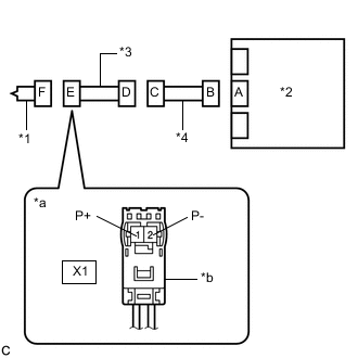
*1 Instrument Panel Passenger Airbag Assembly *2 Airbag ECU Assembly *a Front view of wire harness connector
(to Instrument Panel Passenger Airbag Assembly)
*b Color: Orange Disconnect the instrument panel wire from the airbag ECU assembly.
-
Check for a short to B+ in the circuit.
-
Connect the cable to the negative (-) auxiliary battery terminal.
-
Turn the power switch on (IG).
-
Measure the voltage according to the value(s) in the table below.
Standard Voltage Tester Connection Condition Specified Condition X1-1 (P+) - Body ground Power switch on (IG) Below 1 V X1-2 (P-) - Body ground Power switch on (IG) Below 1 V -
Turn the power switch off.
-
Disconnect the cable from the negative (-) auxiliary battery terminal.
CAUTION:
Wait at least 90 seconds after disconnecting the cable from the negative (-) auxiliary battery terminal to disable the SRS system.
-
-
Check for an open in the circuit.
-
Measure the resistance according to the value(s) in the table below.
Standard Resistance Tester Connection Condition Specified Condition X1-1 (P+) - X1-2 (P-) Always Below 1 Ω
-
-
Check for a short to ground in the circuit.
-
Measure the resistance according to the value(s) in the table below.
Standard Resistance Tester Connection Condition Specified Condition X1-1 (P+) - Body ground Always 1 MΩ or higher X1-2 (P-) - Body ground Always 1 MΩ or higher
-
-
Check for a short in the circuit.
-
Release the activation prevention mechanism built into connector B.
-
Measure the resistance according to the value(s) in the table below.
Standard Resistance Tester Connection Condition Specified Condition X1-1 (P+) - X1-2 (P-) Always 1 MΩ or higher -
Restore the released activation prevention mechanism of connector B to the original condition.
Result Proceed to OK NG -
NG
CHECK INSTRUMENT PANEL WIRE Click here
OK
-
-
CHECK DTC
-
*1 Instrument Panel Passenger Airbag Assembly *2 Airbag ECU Assembly Connect the connectors to the instrument panel passenger airbag assembly and airbag ECU assembly.
-
Connect the cable to the negative (-) auxiliary battery terminal.
-
Clear the DTCs stored in memory.
Body Electrical > SRS Airbag > Clear DTCs -
Turn the power switch off.
-
Turn the power switch on (IG), and wait for at least 60 seconds.
-
Check for DTCs.
Body Electrical > SRS Airbag > Trouble CodesOK DTC B1805/52, B1806/52, B1807/52 or B1808/52 is not output. Tech Tips
Codes other than DTCs B1805/52, B1806/52, B1807/52 and B1808/52 may be output at this time, but they are not related to this check.
Result Proceed to OK NG
OK
USE SIMULATION METHOD TO CHECK Click here
NG
REPLACE AIRBAG ECU ASSEMBLY Click here
-
-
CHECK INSTRUMENT PANEL WIRE
-
*1 Instrument Panel Passenger Airbag Assembly *2 Airbag ECU Assembly *3 No. 2 Instrument Panel Wire *4 Instrument Panel Wire *a Front view of wire harness connector
(to No. 2 Instrument Panel Wire)
Disconnect the No. 2 instrument panel wire from the instrument panel wire.
-
Check for a short to B+ in the circuit.
-
Connect the cable to the negative (-) auxiliary battery terminal.
-
Turn the power switch on (IG).
-
Measure the voltage according to the value(s) in the table below.
Standard Voltage Tester Connection Condition Specified Condition FX1 -1 (P+) - Body ground Power switch on (IG) Below 1 V FX1 -2 (P-) - Body ground Power switch on (IG) Below 1 V -
Turn the power switch off.
-
Disconnect the cable from the negative (-) auxiliary battery terminal.
CAUTION:
Wait at least 90 seconds after disconnecting the cable from the negative (-) auxiliary battery terminal to disable the SRS system.
-
-
Check for an open in the circuit.
-
Measure the resistance according to the value(s) in the table below.
Standard Resistance Tester Connection Condition Specified Condition FX1 -1 (P+) - FX1 -2 (P-) Always Below 1 Ω
-
-
Check for a short to ground in the circuit.
-
Measure the resistance according to the value(s) in the table below.
Standard Resistance Tester Connection Condition Specified Condition FX1 -1 (P+) - Body ground Always 1 MΩ or higher FX1 -2 (P-) - Body ground Always 1 MΩ or higher
-
-
Check for a short in the circuit.
-
Release the activation prevention mechanism built into connector B.
-
Measure the resistance according to the value(s) in the table below.
Standard Resistance Tester Connection Condition Specified Condition FX1 -1 (P+) - FX1 -2 (P-) Always 1 MΩ or higher -
Restore the released activation prevention mechanism of connector B to the original condition.
Result Proceed to OK NG -
NG
REPLACE INSTRUMENT PANEL WIRE
OK
-
-
CHECK NO. 2 INSTRUMENT PANEL WIRE
-
*1 Instrument Panel Passenger Airbag Assembly *2 Airbag ECU Assembly *3 No. 2 Instrument Panel Wire *4 Instrument Panel Wire *a Front view of wire harness connector
(to Instrument Panel Passenger Airbag Assembly)
*b Color: Orange Check for a short to B+ in the circuit.
-
Connect the cable to the negative (-) auxiliary battery terminal.
-
Turn the power switch on (IG).
-
Measure the voltage according to the value(s) in the table below.
Standard Voltage Tester Connection Condition Specified Condition X1-1 (P+) - Body ground Power switch on (IG) Below 1 V X1-2 (P-) - Body ground Power switch on (IG) Below 1 V -
Turn the power switch off.
-
Disconnect the cable from the negative (-) auxiliary battery terminal.
CAUTION:
Wait at least 90 seconds after disconnecting the cable from the negative (-) auxiliary battery terminal to disable the SRS system.
-
-
Check for an open in the circuit.
-
Measure the resistance according to the value(s) in the table below.
Standard Resistance Tester Connection Condition Specified Condition X1-1 (P+) - X1-2 (P-) Always Below 1 Ω
-
-
Check for a short to ground in the circuit.
-
Measure the resistance according to the value(s) in the table below.
Standard Resistance Tester Connection Condition Specified Condition X1-1 (P+) - Body ground Always 1 MΩ or higher X1-2 (P-) - Body ground Always 1 MΩ or higher
-
-
Check for a short in the circuit.
-
Release the activation prevention mechanism built into connector D.
-
Measure the resistance according to the value(s) in the table below.
Standard Resistance Tester Connection Condition Specified Condition X1-1 (P+) - X1-2 (P-) Always 1 MΩ or higher -
Restore the released activation prevention mechanism of connector D to the original condition.
Result Proceed to OK NG -
OK
USE SIMULATION METHOD TO CHECK Click here
NG
REPLACE NO. 2 INSTRUMENT PANEL WIRE
-