METER / GAUGE SYSTEM Odo/Trip Switch Malfunction
DESCRIPTION
The combination meter assembly (meter circuit plate) detects ODO/TRIP switch signals via a direct line.
WIRING DIAGRAM
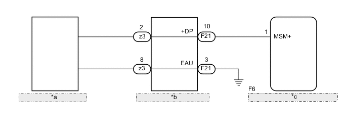
| *a | Trip Switch (Steering Pad Switch Assembly) |
| *b | Spiral Cable Sub-assembly |
| *c | Combination Meter Assembly (Meter Circuit Plate) |
PROCEDURE
-
INSPECT TRIP SWITCH (STEERING PAD SWITCH ASSEMBLY)
-
Remove the trip switch (steering pad switch assembly).
-
Inspect the trip switch (steering pad switch assembly).
Result Proceed to OK NG
NG 
REPLACE TRIP SWITCH (STEERING PAD SWITCH ASSEMBLY) Click here
OK 
-
-
INSPECT SPIRAL CABLE SUB-ASSEMBLY
-
Remove the spiral cable sub-assembly.
-
Inspect the spiral cable sub-assembly.
Result Proceed to OK NG
NG
REPLACE SPIRAL CABLE SUB-ASSEMBLY Click here
OK
-
-
CHECK HARNESS AND CONNECTOR (COMBINATION METER ASSEMBLY (METER CIRCUIT PLATE) - SPIRAL CABLE SUB-ASSEMBLY)
-
Disconnect the F6 combination meter assembly (meter circuit plate) connector.
-
Measure the resistance according to the value(s) in the table below.
Standard Resistance Tester Connection Condition Specified Condition F6-1 (MSM+) - F21-10 (+DP) Always Below 1 Ω F6-1 (MSM+) or F21-10 (+DP) - Body ground Always 10 kΩ or higher Result Proceed to OK NG
OK
REPLACE COMBINATION METER ASSEMBLY (METER CIRCUIT PLATE) Click here
NG
REPAIR OR REPLACE HARNESS OR CONNECTOR
-