METER / GAUGE SYSTEM Malfunction in Water Temperature Warning Light
DESCRIPTION
In this circuit, the combination meter assembly (meter circuit plate) receives engine coolant temperature signals from the ECM via CAN communication. The combination meter assembly (meter circuit plate) displays an engine coolant temperature warning based on the data received from the ECM.
WIRING DIAGRAM
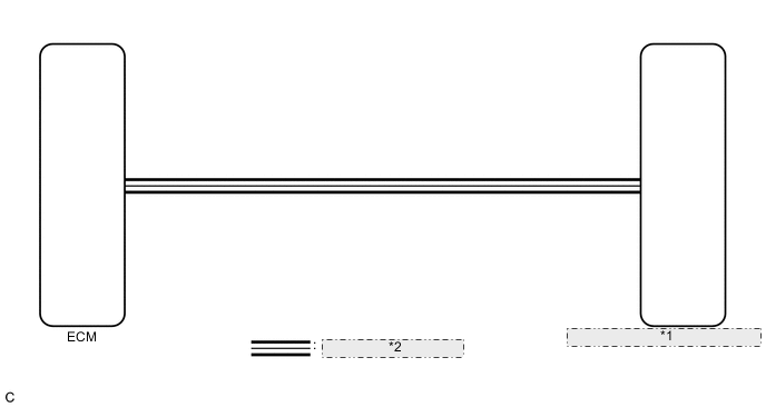
| *1 | Combination Meter Assembly (Meter Circuit Plate) |
| *2 | CAN Communication Line |
CAUTION / NOTICE / HINT
Tech Tips
If there is an open or short in the engine coolant temperature sensor circuit, the ECM stores DTCs. Troubleshoot the SFI system.
w/ Canister Pump Module: Click here
w/o Canister Pump Module: Click here
PROCEDURE
-
CHECK CAN COMMUNICATION SYSTEM
-
Check if CAN communication system DTCs are output.
Body Electrical > Combination Meter > Trouble CodesResult Result Proceed to CAN communication system DTCs are not output. A CAN communication system DTCs are output. B
B 
GO TO CAN COMMUNICATION SYSTEM Click here
A 
-
-
SYSTEM CHECK
-
Check the engine coolant temperature hot warning light.
Result Result Proceed to Engine coolant temperature hot warning light does not come on. A Engine coolant temperature hot warning light blinks or remains on. B
B 
GO TO STEP 4 Click here
A
-
-
PERFORM ACTIVE TEST USING GTS (INDICAT. LAMP COOLANT HOT)
-
Connect the GTS to the DLC3.
-
Turn the power switch on (IG).
-
Turn the GTS on.
-
Enter the following menus: Body Electrical / Combination Meter / Active Test.
-
Perform the Active Test according to the display on the GTS.
Body Electrical > Combination Meter > Active TestTester Display Measurement Item Control Range Diagnostic Note Indicat. Lamp Coolant Hot Engine coolant temperature hot warning light OFF or ON -
Body Electrical > Combination Meter > Active TestTester Display Indicat. Lamp Coolant Hot OK Engine coolant temperature hot warning light operation is normal. Result Proceed to OK NG
NG
REPLACE COMBINATION METER ASSEMBLY (METER CIRCUIT PLATE) Click here
OK
-
-
CHECK FOR DTC
-
Check if SFI system DTCs are output.
w/ Canister Pump Module: Click here
w/o Canister Pump Module: Click here
Powertrain > Engine > Trouble CodesResult Result Proceed to SFI system DTCs are not output. A SFI system DTCs are output. B
B
GO TO SFI SYSTEM w/ Canister Pump Module: Click here
GO TO SFI SYSTEM w/o Canister Pump Module: Click hereA
-
-
READ VALUE USING GTS (COOLANT TEMP, COOLANT TEMPERATURE)
-
Connect the GTS to the DLC3.
-
Turn the power switch on (IG).
-
Turn the GTS on.
-
Enter the following menus:
-
for Engine: Powertrain / Engine / Data List.
-
for Combination Meter: Body Electrical / Combination Meter / Data List.
-
-
Read the Data List according to the display on the GTS.
Powertrain > Engine > Data ListTester Display Measurement Item Range Normal Condition Diagnostic Note Coolant Temperature Engine coolant temperature Min.: -40°C (-40°F), Max.: 140°C (284°F) 75 to 100°C (167 to 212°F): After warming up This is the engine coolant temperature.
Tech Tips
-
After warming up the engine, the engine coolant temperature will be 75 to 100°C (167 to 212°F).
-
After a long soak, the engine coolant temperature, intake air temperature and ambient air temperature will be approximately equal.
-
If the value is -40°C (-40°F), or higher than 135°C (275°F), the sensor circuit is open or shorted.
-
Check if the engine overheats if the value indicated is higher than 135°C (275°F).
Powertrain > Engine > Data ListTester Display Coolant Temperature
Body Electrical > Combination Meter > Data ListTester Display Measurement Item Range Normal Condition Diagnostic Note Coolant Temperature Engine coolant temperature Min.: 0°C (32°F), Max.: 127.5°C (261.5°F) 75 to 100°C (167 to 212°F) (After warming up engine) -
Body Electrical > Combination Meter > Data ListTester Display Coolant Temperature Result Result Proceed to The Data List values of the ECUs do not match. A The Data List values of the ECUs match. B Tech Tips
-
When the Data List values of the ECUs match, an internal malfunction of the ECM is suspected.
-
When the Data List values of the ECUs do not match, a signal output malfunction of the ECM or an internal malfunction of the combination meter assembly (meter circuit plate) is suspected.
-
B
REPLACE ECM Click here
A
-
-
REPLACE COMBINATION METER ASSEMBLY (METER CIRCUIT PLATE)
-
Replace the combination meter assembly (meter circuit plate) with a new or known good one.
OK The operation of the engine coolant temperature hot warning light returns to normal. Result Proceed to OK NG
OK
END
NG
REPLACE ECM Click here
-