METER / GAUGE SYSTEM, Diagnostic DTC:B1503
| DTC Code | DTC Name |
|---|---|
| B1503 | Exhaust Heat Management Warning Detected |
DESCRIPTION
This DTC is stored when the combination meter assembly (meter circuit plate) detects a malfunction in the engine coolant temperature sensor that is connected to the combination meter assembly (meter circuit plate) via a direct line.
| DTC No. | Detection Item | DTC Detection Condition | Trouble Area | Memory | Note |
|---|---|---|---|---|---|
| B1503 | Exhaust Heat Management Warning Detected | When IG voltage is 9.5 V or more and either of the following conditions is detected:
|
|
DTC stored | w/ Exhaust Heat Recirculation System |
Tech Tips
This DTC is for the engine coolant temperature sensor which is used to detect the engine coolant temperature for the exhaust heat recirculation system, not for the engine coolant temperature sensor which is used for the SFI system.
WIRING DIAGRAM
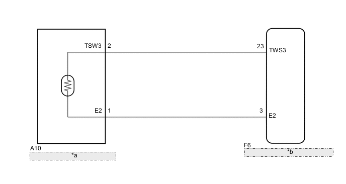
| *a | Engine Coolant Temperature Sensor |
| *b | Combination Meter Assembly (Meter Circuit Plate) |
PROCEDURE
-
READ VALUE USING GTS (COOLANT TEMPERATURE)
-
Put the engine in inspection mode (maintenance mode).
-
Connect the GTS to the DLC3.
-
Turn the power switch on (IG).
-
Turn the GTS on.
-
Enter the following menus: Body Electrical / Combination Meter / Data List.
-
Read the Data List according to the display on the GTS.
Body Electrical > Combination Meter > Data ListTester Display Measurement Item Range Normal Condition Diagnostic Note Coolant Temperature Engine coolant temperature 0 to 127.5°C (0 to 261.5°F) 75 to 100°C (167 to 212°F) (After warming up engine) -
Body Electrical > Combination Meter > Data ListTester Display Coolant Temperature OK Engine coolant temperature displayed on the GTS is 75 to 100°C (167 to 212°F) after the engine is warmed. Note
If the engine coolant temperature exceeds 100°C, the cooling system is malfunctioning. Stop the engine immediately.
Tech Tips
The coolant temperature value in this inspection is the data sent from the engine coolant temperature sensor for the SFI system.
Result Proceed to OK NG
NG 
GO TO EXHAUST HEAT RECIRCULATION SYSTEM Click here
OK 
-
-
CHECK HARNESS AND CONNECTOR (COMBINATION METER ASSEMBLY (METER CIRCUIT PLATE) - ENGINE COOLANT TEMPERATURE SENSOR)
-
Disconnect the F6 combination meter assembly (meter circuit plate) connector.
-
Disconnect the A10 engine coolant temperature sensor connector.
-
Measure the resistance according to the value(s) in the table below.
Standard Resistance Tester Connection Condition Specified Condition F6-23 (TWS3) - A10-2 (TSW3) Always Below 1 Ω F6-3 (E2) - A10-1 (E2) Always Below 1 Ω F6-23 (TWS3) or A10-2 (TSW3) - Body ground Always 10 kΩ or higher F6-3 (E2) or A10-1 (E2) - Body ground Always 10 kΩ or higher Result Proceed to OK NG
NG
REPAIR OR REPLACE HARNESS OR CONNECTOR
OK
-
-
INSPECT ENGINE COOLANT TEMPERATURE SENSOR
-
Remove the engine coolant temperature sensor.
-
Inspect the engine coolant temperature sensor.
Result Proceed to OK NG
OK
REPLACE COMBINATION METER ASSEMBLY (METER CIRCUIT PLATE) Click here
NG
REPLACE ENGINE COOLANT TEMPERATURE SENSOR Click here
-