METER / GAUGE SYSTEM, Diagnostic DTC:B1507, B1508
| DTC Code | DTC Name |
|---|---|
| B1507 | Open in Turn Signal Circuit |
| B1508 | Short in Turn Signal / Hazard Flasher Circuit |
DESCRIPTION
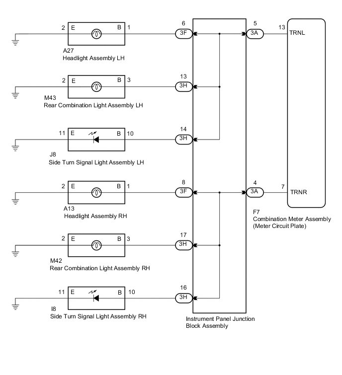
These DTCs are stored when the combination meter assembly (meter circuit plate) detects an open in a turn signal light circuit, or a short in a turn signal light circuit or the hazard warning light circuit.
| DTC No. | Detection Item | DTC Detection Condition | Trouble Area | Memory | Note |
|---|---|---|---|---|---|
| B1507 | Open in Turn Signal Circuit | When IG voltage is 9.5 V or more and the following condition is detected:
|
|
DTC stored | - |
| B1508 | Short in Turn Signal / Hazard Flasher Circuit | When IG voltage is 9.5 V or more and the following condition is detected:
|
|
DTC stored | - |
WIRING DIAGRAM
CAUTION / NOTICE / HINT
Note
Inspect the bulbs for this system before performing the following procedure.
Side turn signal light assembly: Click here
Rear combination light assembly: Click here
PROCEDURE
-
INSPECT LIGHTS
-
Inspect the illumination of each turn signal light.
Result Result Proceed to All RH turn signal lights do not blink. A All LH turn signal lights do not blink. B RH side turn signal light does not blink or flash at the correct speed. C LH side turn signal light does not blink or flash at the correct speed. D
B 
CHECK HARNESS AND CONNECTOR (COMBINATION METER ASSEMBLY (METER CIRCUIT PLATE) - INSTRUMENT PANEL JUNCTION BLOCK ASSEMBLY OR BODY GROUND) Click here
C
CHECK TURN SIGNAL LIGHTS (RH SIDE) Click here
D
CHECK TURN SIGNAL LIGHTS (LH SIDE) Click here
A 
-
-
CHECK HARNESS AND CONNECTOR (COMBINATION METER ASSEMBLY (METER CIRCUIT PLATE) - INSTRUMENT PANEL JUNCTION BLOCK ASSEMBLY OR BODY GROUND)
-
Disconnect the F7 combination meter assembly (meter circuit plate) connector.
-
Disconnect the 3A instrument panel junction block assembly connector.
-
Measure the resistance according to the value(s) in the table below.
Standard Resistance (Check for Open) Tester Connection Condition Specified Condition F7-7 (TRNR) - 3A-4 Always Below 1 Ω Standard Resistance (Check for Short) Tester Connection Condition Specified Condition F7-7 (TRNR) or 3A-4 - Body ground Always 10 kΩ or higher Result Proceed to OK NG
NG 
REPAIR OR REPLACE HARNESS OR CONNECTOR
OK
-
-
INSPECT INSTRUMENT PANEL JUNCTION BLOCK ASSEMBLY
-
Remove the instrument panel junction block assembly.
Tech Tips
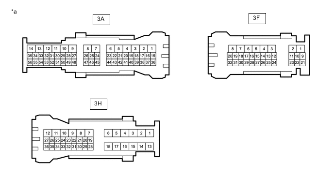
*a Component without harness connected
(Instrument Panel Junction Block Assembly)
- - -
Measure the resistance according to the value(s) in the table below.
Standard Resistance Tester Connection Condition Specified Condition 3A-4 - 3F-8 Always Below 1 Ω 3A-4 - 3H-17 Always Below 1 Ω 3A-4 - 3H-16 Always Below 1 Ω Result Proceed to OK NG
OK
REPLACE COMBINATION METER ASSEMBLY (METER CIRCUIT PLATE) Click here
NG
REPLACE INSTRUMENT PANEL JUNCTION BLOCK ASSEMBLY Click here
-
-
CHECK HARNESS AND CONNECTOR (COMBINATION METER ASSEMBLY (METER CIRCUIT PLATE) - INSTRUMENT PANEL JUNCTION BLOCK ASSEMBLY OR BODY GROUND)
-
Disconnect the F7 combination meter assembly (meter circuit plate) connector.
-
Disconnect the 3A instrument panel junction block assembly connector.
-
Measure the resistance according to the value(s) in the table below.
Standard Resistance (Check for Open) Tester Connection Condition Specified Condition F7-13 (TRNL) - 3A-5 Always Below 1 Ω Standard Resistance (Check for Short) Tester Connection Condition Specified Condition F7-13 (TRNL) or 3A-5 - Body ground Always 10 kΩ or higher Result Proceed to OK NG
NG
REPAIR OR REPLACE HARNESS OR CONNECTOR
OK
-
-
INSPECT INSTRUMENT PANEL JUNCTION BLOCK ASSEMBLY
-
Remove the instrument panel junction block assembly.
Tech Tips
*a Component without harness connected
(Instrument Panel Junction Block Assembly)
- - -
Measure the resistance according to the value(s) in the table below.
Standard Resistance Tester Connection Condition Specified Condition 3A-5 - 3F-6 Always Below 1 Ω 3A-5 - 3H-13 Always Below 1 Ω 3A-5 - 3H-14 Always Below 1 Ω Result Proceed to OK NG
OK
REPLACE COMBINATION METER ASSEMBLY (METER CIRCUIT PLATE) Click here
NG
REPLACE INSTRUMENT PANEL JUNCTION BLOCK ASSEMBLY Click here
-
-
CHECK TURN SIGNAL LIGHTS (RH SIDE)
-
Turn the power switch on (IG).
-
Set the headlight dimmer switch assembly to the right turn switch position.
-
Check the operation of the turn signal lights (RH side).
Result Result Proceed to Front turn signal light RH does not blink or flash at the correct speed. A Side turn signal light RH does not blink or flash at the correct speed. B Rear turn signal light RH does not blink or flash at the correct speed. C
B
CHECK HARNESS AND CONNECTOR (SIDE TURN SIGNAL LIGHT ASSEMBLY RH - INSTRUMENT PANEL JUNCTION BLOCK ASSEMBLY OR BODY GROUND) Click here
C
CHECK HARNESS AND CONNECTOR (REAR COMBINATION LIGHT ASSEMBLY RH - INSTRUMENT PANEL JUNCTION BLOCK ASSEMBLY OR BODY GROUND) Click here
A
-
-
CHECK HARNESS AND CONNECTOR (HEADLIGHT ASSEMBLY RH - INSTRUMENT PANEL JUNCTION BLOCK ASSEMBLY OR BODY GROUND)
-
Disconnect the A13 headlight assembly RH connector.
-
Disconnect the 3F instrument panel junction block assembly connector.
-
Measure the resistance according to the value(s) in the table below.
Standard Resistance (Check for Open) Tester Connection Condition Specified Condition A13-1 (B) - 3F-8 Always Below 1 Ω A13-2 (E) - Body ground Always Below 1 Ω Standard Resistance (Check for Short) Tester Connection Condition Specified Condition A13-1 (B) or 3F-8 - Body ground Always 10 kΩ or higher Result Proceed to OK NG
NG
REPAIR OR REPLACE HARNESS OR CONNECTOR
OK
-
-
INSPECT INSTRUMENT PANEL JUNCTION BLOCK ASSEMBLY
-
Remove the instrument panel junction block assembly.
Tech Tips
-
Measure the resistance according to the value(s) in the table below.
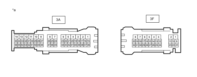
*a Component without harness connected
(Instrument Panel Junction Block Assembly)
- - Standard Resistance Tester Connection Condition Specified Condition 3A-4 - 3F-8 Always Below 1 Ω Result Proceed to OK NG
OK
REPLACE HEADLIGHT ASSEMBLY RH Click here
NG
REPLACE INSTRUMENT PANEL JUNCTION BLOCK ASSEMBLY Click here
-
-
CHECK HARNESS AND CONNECTOR (SIDE TURN SIGNAL LIGHT ASSEMBLY RH - INSTRUMENT PANEL JUNCTION BLOCK ASSEMBLY OR BODY GROUND)
-
Disconnect the I8 side turn signal light assembly RH connector.
-
Disconnect the 3H instrument panel junction block assembly connector.
-
Measure the resistance according to the value(s) in the table below.
Standard Resistance (Check for Open) Tester Connection Condition Specified Condition I8-10 (B) - 3H-16 Always Below 1 Ω I8-11 (E) - Body ground Always Below 1 Ω Standard Resistance (Check for Short) Tester Connection Condition Specified Condition I8-10 (B) or 3H-16 - Body ground Always 10 kΩ or higher Result Proceed to OK NG
NG
REPAIR OR REPLACE HARNESS OR CONNECTOR
OK
-
-
INSPECT INSTRUMENT PANEL JUNCTION BLOCK ASSEMBLY
-
Remove the instrument panel junction block assembly.
Tech Tips
-
Measure the resistance according to the value(s) in the table below.
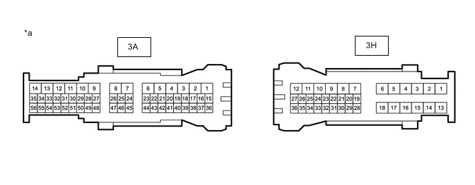
*a Component without harness connected
(Instrument Panel Junction Block Assembly)
- - Standard Resistance Tester Connection Condition Specified Condition 3A-4 - 3H-16 Always Below 1 Ω Result Proceed to OK NG
OK
REPLACE SIDE TURN SIGNAL LIGHT ASSEMBLY RH Click here
NG
REPLACE INSTRUMENT PANEL JUNCTION BLOCK ASSEMBLY Click here
-
-
CHECK HARNESS AND CONNECTOR (REAR COMBINATION LIGHT ASSEMBLY RH - INSTRUMENT PANEL JUNCTION BLOCK ASSEMBLY OR BODY GROUND)
-
Disconnect the M42 rear combination light assembly RH connector.
-
Disconnect the 3H instrument panel junction block assembly connector.
-
Measure the resistance according to the value(s) in the table below.
Standard Resistance (Check for Open) Tester Connection Condition Specified Condition M42-3 (B) - 3H-17 Always Below 1 Ω M42-2 (E) - Body ground Always Below 1 Ω Standard Resistance (Check for Short) Tester Connection Condition Specified Condition M42-3 (B) or 3H-17 - Body ground Always 10 kΩ or higher Result Proceed to OK NG
NG
REPAIR OR REPLACE HARNESS OR CONNECTOR
OK
-
-
INSPECT INSTRUMENT PANEL JUNCTION BLOCK ASSEMBLY
-
Remove the instrument panel junction block assembly.
Tech Tips
-
Measure the resistance according to the value(s) in the table below.
*a Component without harness connected
(Instrument Panel Junction Block Assembly)
- - Standard Resistance Tester Connection Condition Specified Condition 3A-4 - 3H-17 Always Below 1 Ω Result Proceed to OK NG
OK
REPLACE REAR COMBINATION LIGHT ASSEMBLY RH Click here
NG
REPLACE INSTRUMENT PANEL JUNCTION BLOCK ASSEMBLY Click here
-
-
CHECK TURN SIGNAL LIGHTS (LH SIDE)
-
Turn the power switch on (IG).
-
Set the headlight dimmer switch assembly to the left turn switch position.
-
Check the operation of the turn signal lights (LH side).
Result Result Proceed to Front turn signal light LH does not blink or flash at the correct speed. A Side turn signal light LH does not blink or flash at the correct speed. B Rear turn signal light LH does not blink or flash at the correct speed. C
B
CHECK HARNESS AND CONNECTOR (SIDE TURN SIGNAL LIGHT ASSEMBLY LH - INSTRUMENT PANEL JUNCTION BLOCK ASSEMBLY OR BODY GROUND) Click here
C
CHECK HARNESS AND CONNECTOR (REAR COMBINATION LIGHT ASSEMBLY LH - INSTRUMENT PANEL JUNCTION BLOCK ASSEMBLY OR BODY GROUND) Click here
A
-
-
CHECK HARNESS AND CONNECTOR (HEADLIGHT ASSEMBLY LH - INSTRUMENT PANEL JUNCTION BLOCK ASSEMBLY OR BODY GROUND)
-
Disconnect the A27 headlight assembly LH connector.
-
Disconnect the 3F instrument panel junction block assembly connector.
-
Measure the resistance according to the value(s) in the table below.
Standard Resistance (Check for Open) Tester Connection Condition Specified Condition A27-1 (B) - 3F-6 Always Below 1 Ω A27-2 (E) - Body ground Always Below 1 Ω Standard Resistance (Check for Short) Tester Connection Condition Specified Condition A27-1 (B) or 3F-6 - Body ground Always 10 kΩ or higher Result Proceed to OK NG
NG
REPAIR OR REPLACE HARNESS OR CONNECTOR
OK
-
-
INSPECT INSTRUMENT PANEL JUNCTION BLOCK ASSEMBLY
-
Remove the instrument panel junction block assembly.
Tech Tips
-
Measure the resistance according to the value(s) in the table below.
*a Component without harness connected
(Instrument Panel Junction Block Assembly)
- - Standard Resistance Tester Connection Condition Specified Condition 3A-5 - 3F-6 Always Below 1 Ω Result Proceed to OK NG
OK
REPLACE HEADLIGHT ASSEMBLY LH Click here
NG
REPLACE INSTRUMENT PANEL JUNCTION BLOCK ASSEMBLY Click here
-
-
CHECK HARNESS AND CONNECTOR (SIDE TURN SIGNAL LIGHT ASSEMBLY LH - INSTRUMENT PANEL JUNCTION BLOCK ASSEMBLY OR BODY GROUND)
-
Disconnect the J8 side turn signal light assembly LH connector.
-
Disconnect the 3H instrument panel junction block assembly connector.
-
Measure the resistance according to the value(s) in the table below.
Standard Resistance (Check for Open) Tester Connection Condition Specified Condition J8-10 (B) - 3H-14 Always Below 1 Ω J8-11 (E) - Body ground Always Below 1 Ω Standard Resistance (Check for Short) Tester Connection Condition Specified Condition J8-10 (B) or 3H-14 - Body ground Always 10 kΩ or higher Result Proceed to OK NG
NG
REPAIR OR REPLACE HARNESS OR CONNECTOR
OK
-
-
INSPECT INSTRUMENT PANEL JUNCTION BLOCK ASSEMBLY
-
Remove the instrument panel junction block assembly.
Tech Tips
-
Measure the resistance according to the value(s) in the table below.
*a Component without harness connected
(Instrument Panel Junction Block Assembly)
- - Standard Resistance Tester Connection Condition Specified Condition 3A-5 - 3H-14 Always Below 1 Ω Result Proceed to OK NG
OK
REPLACE SIDE TURN SIGNAL LIGHT ASSEMBLY LH Click here
NG
REPLACE INSTRUMENT PANEL JUNCTION BLOCK ASSEMBLY Click here
-
-
CHECK HARNESS AND CONNECTOR (REAR COMBINATION LIGHT ASSEMBLY LH - INSTRUMENT PANEL JUNCTION BLOCK ASSEMBLY OR BODY GROUND)
-
Disconnect the M43 rear combination light assembly LH connector.
-
Disconnect the 3H instrument panel junction block assembly connector.
-
Measure the resistance according to the value(s) in the table below.
Standard Resistance (Check for Open) Tester Connection Condition Specified Condition M43-3 (B) - 3H-13 Always Below 1 Ω M43-2 (E) - Body ground Always Below 1 Ω Standard Resistance (Check for Short) Tester Connection Condition Specified Condition M43-3 (B) or 3H-13 - Body ground Always 10 kΩ or higher Result Proceed to OK NG
NG
REPAIR OR REPLACE HARNESS OR CONNECTOR
OK
-
-
INSPECT INSTRUMENT PANEL JUNCTION BLOCK ASSEMBLY
-
Remove the instrument panel junction block assembly.
Tech Tips
-
Measure the resistance according to the value(s) in the table below.
*a Component without harness connected
(Instrument Panel Junction Block Assembly)
- - Standard Resistance Tester Connection Condition Specified Condition 3A-5 - 3H-13 Always Below 1 Ω Result Proceed to OK NG
OK
REPLACE REAR COMBINATION LIGHT ASSEMBLY LH Click here
NG
REPLACE INSTRUMENT PANEL JUNCTION BLOCK ASSEMBLY Click here
-