POWER DOOR LOCK CONTROL SYSTEM SYSTEM DIAGRAM
-
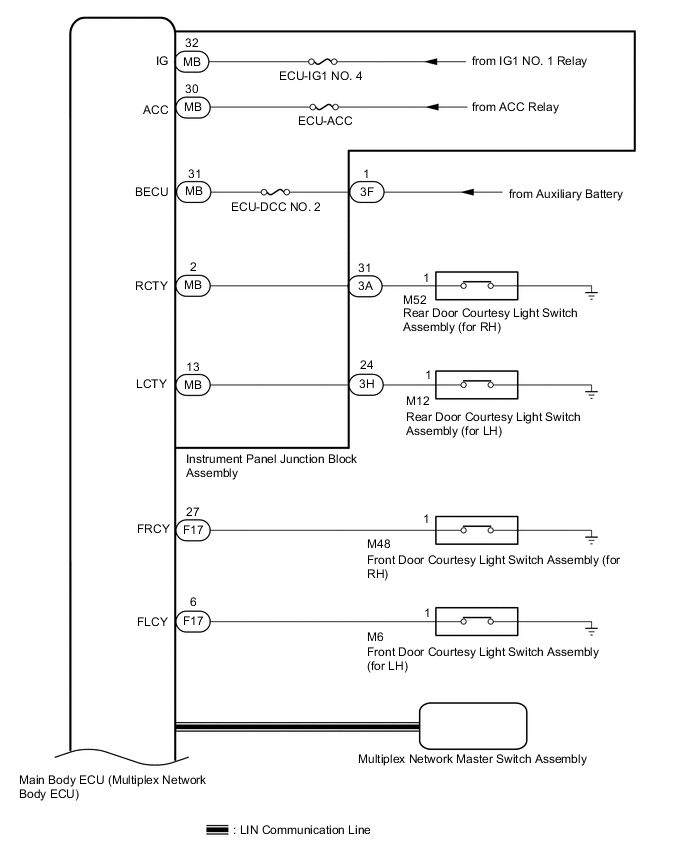
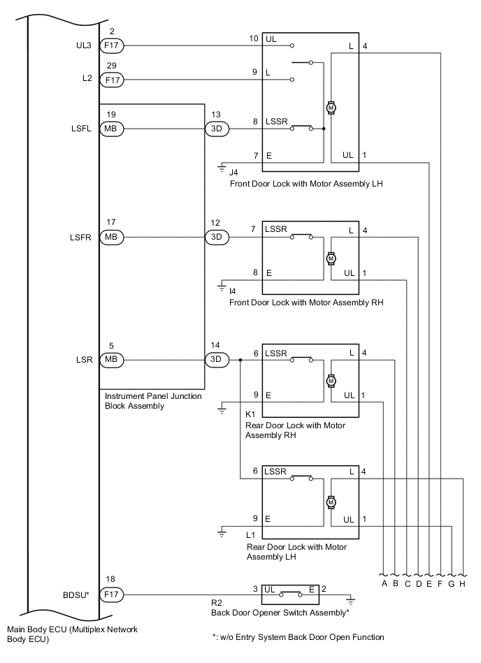
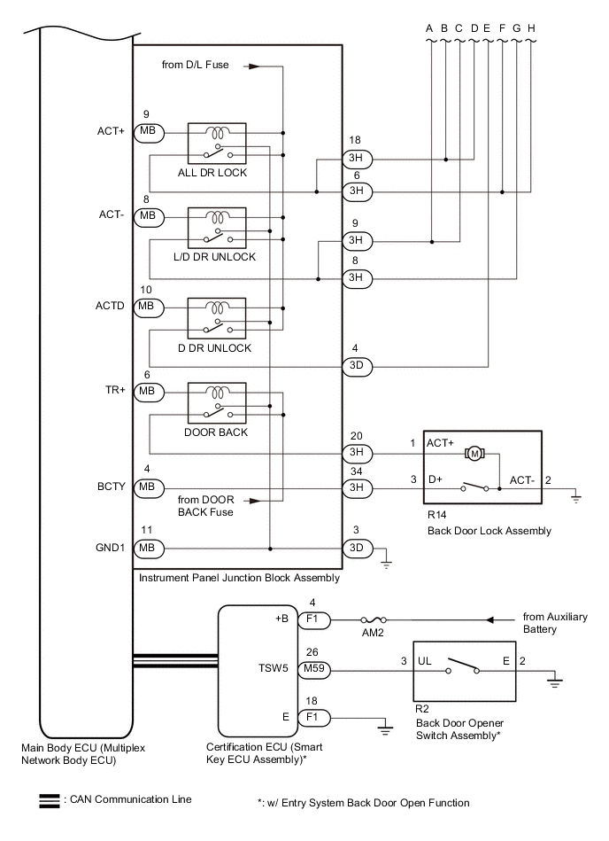
Power Door Lock Control System (for LHD and w/o Canister Pump Module)
-
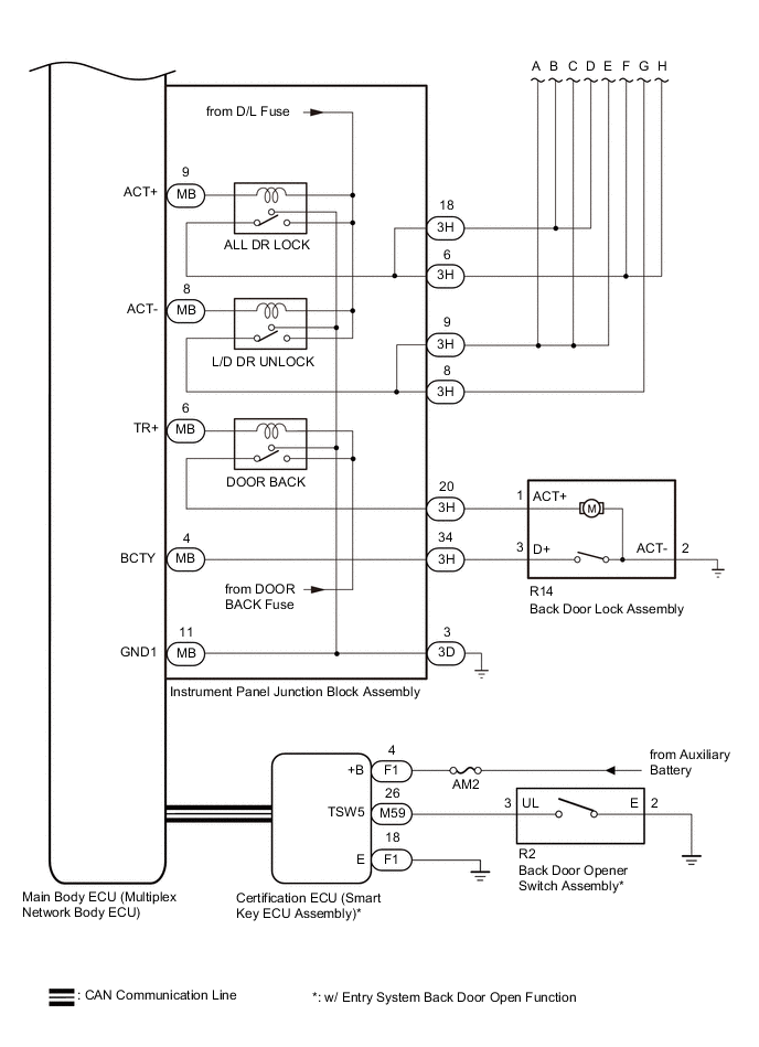
Power Door Lock Control System (for LHD and w/ Canister Pump Module)
-
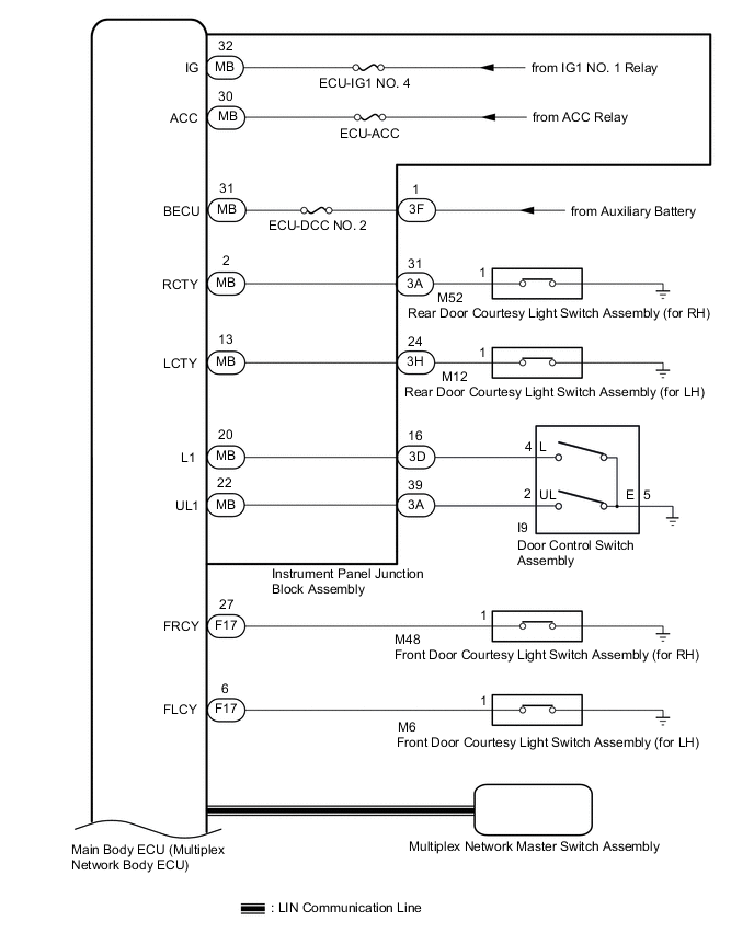
Power Door Lock Control System (for RHD)
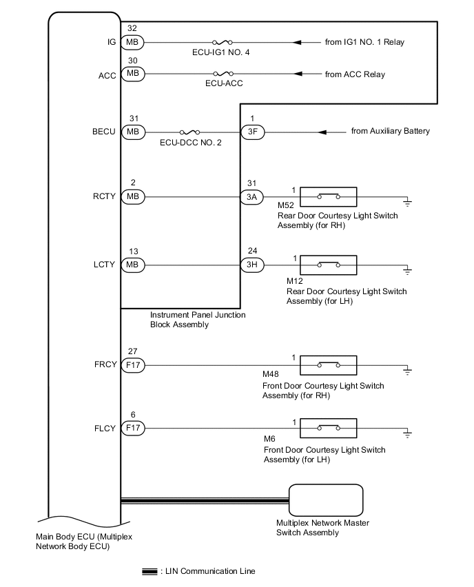
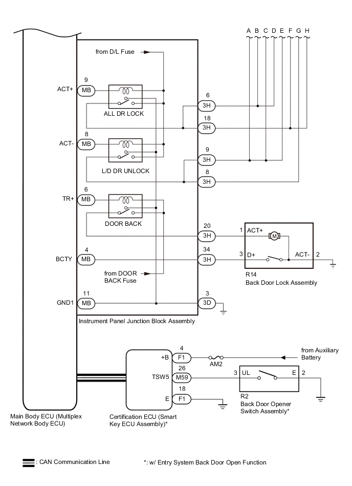
Communication Table Sender Receiver Signal Line Multiplex Network Master Switch Assembly Main Body ECU (Multiplex Network Body ECU) Door control switch signal LIN Certification ECU (Smart Key ECU Assembly)* Main Body ECU (Multiplex Network Body ECU) Back door opener switch signal CAN
-
*: w/ Entry System Back Door Open Function
-
-
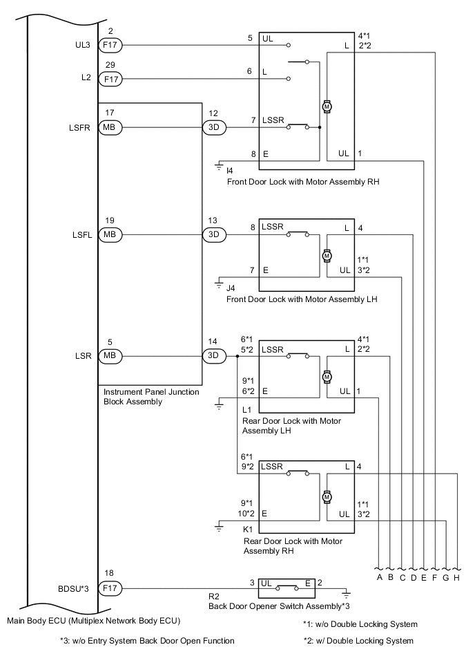
Double Locking System (w/ Double Locking System)
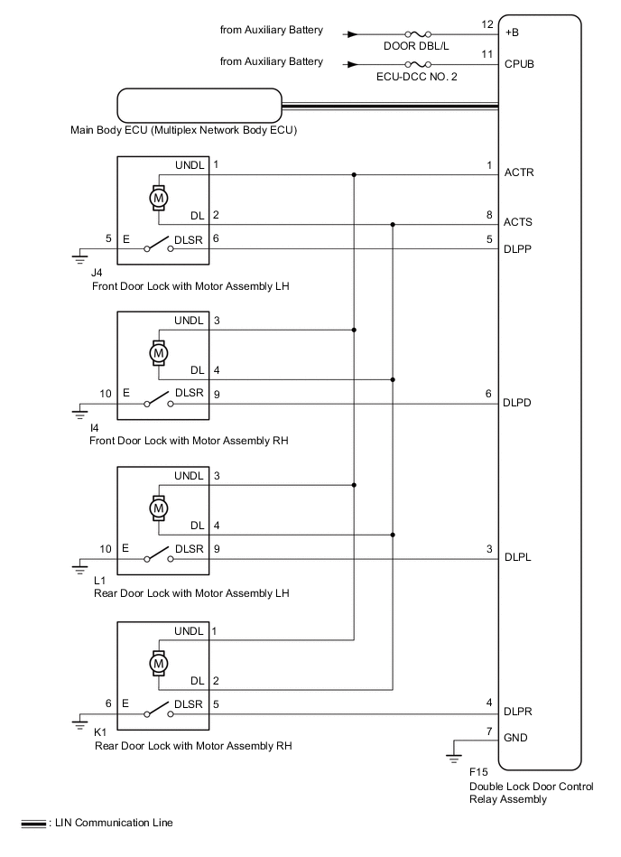
Communication Table Sender Receiver Signal Line Double Lock Door Control Relay Assembly Main Body ECU (Multiplex Network Body ECU) Double lock position switch signal LIN Main Body ECU (Multiplex Network Body ECU) Double Lock Door Control Relay Assembly Double lock set/unset request Signal LIN