LIN COMMUNICATION SYSTEM TERMINALS OF ECU
-
CHECK INSTRUMENT PANEL JUNCTION BLOCK ASSEMBLY AND MAIN BODY ECU (MULTIPLEX NETWORK BODY ECU)
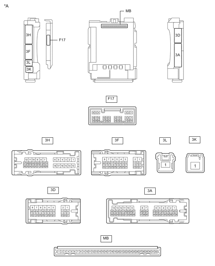
*A for LHD - - 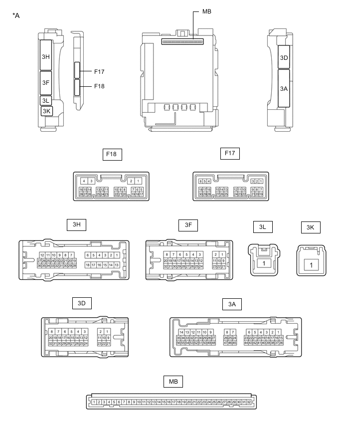
*A for RHD - -
-
Disconnect the MB main body ECU (multiplex network body ECU) connector.
-
Measure the voltage and resistance according to the value(s) in the table below.
Tech Tips
Measure the values on the wire harness side with the connectors disconnected.
Terminal No. (Symbol) Wiring Color Terminal Description Condition Specified Condition MB-11 (GND1) - Body ground - Ground Always Below 1 Ω MB-31 (BECU) - Body ground - Auxiliary battery power supply Power switch off 11 to 14 V MB-30 (ACC) - Body ground - ACC power supply Power switch on (ACC) 11 to 14 V Power switch off Below 1 V MB-32 (IG) - Body ground - IG power supply Power switch on (IG) 11 to 14 V Power switch off Below 1 V -
Reconnect the MB main body ECU (multiplex network body ECU) connector.
-
Check for pulses according to the value(s) in the table below.
Terminal No. (Symbol) Wiring Color Terminal Description Condition Specified Condition 3H-25 - Body ground G - Body ground LIN communication line Power switch on (IG) Pulse generation 3D-17 - Body ground GR - Body ground*1
W - Body ground*2
LIN communication line Power switch on (IG) Pulse generation
-
*1: for LHD
-
*2: for RHD
-
-
-
CHECK POWER WINDOW REGULATOR MOTOR ASSEMBLY (for Driver Door)

*A for LHD *B for RHD
-
for LHD
-
Disconnect the J2 power window regulator motor assembly (for driver door) connector.
-
Measure the voltage and resistance according to the value(s) in the table below.
Tech Tips
Measure the values on the wire harness side with the connector disconnected.
Terminal No. (Symbol) Wiring Color Terminal Description Condition Specified Condition J2-2 (B) - Body ground B - Body ground Auxiliary battery power supply Power switch off 11 to 14 V J2-1 (GND) - Body ground W - Body ground Ground Always Below 1 Ω -
Reconnect the J2 power window regulator motor assembly (for driver door) connector.
-
Check for pulses according to the value(s) in the table below.
Terminal No. (Symbol) Wiring Color Terminal Description Condition Specified Condition J2-9 (LIN) - Body ground SB - Body ground LIN communication line Power switch on (IG) Pulse generation
-
-
for RHD
-
Disconnect the I2 power window regulator motor assembly (for driver door) connector.
-
Measure the voltage and resistance according to the value(s) in the table below.
Tech Tips
Measure the values on the wire harness side with the connector disconnected.
Terminal No. (Symbol) Wiring Color Terminal Description Condition Specified Condition I2-2 (B) - Body ground B - Body ground Auxiliary battery power supply Power switch off 11 to 14 V I2-1 (GND) - Body ground W - Body ground Ground Always Below 1 Ω -
Reconnect the I2 power window regulator motor assembly (for driver door) connector.
-
Check for pulses according to the value(s) in the table below.
Terminal No. (Symbol) Wiring Color Terminal Description Condition Specified Condition I2-9 (LIN) - Body ground SB - Body ground LIN communication line Power switch on (IG) Pulse generation
-
-
-
CHECK POWER WINDOW REGULATOR MOTOR ASSEMBLY (for Front Passenger Door)

*A for LHD *B for RHD
-
for LHD
-
Disconnect the I2 power window regulator motor assembly (for driver door) connector.
-
Measure the voltage and resistance according to the value(s) in the table below.
Tech Tips
Measure the values on the wire harness side with the connector disconnected.
Terminal No. (Symbol) Wiring Color Terminal Description Condition Specified Condition I2-2 (B) - Body ground B - Body ground Auxiliary battery power supply Power switch off 11 to 14 V I2-1 (GND) - Body ground W - Body ground Ground Always Below 1 Ω -
Reconnect the I2 power window regulator motor assembly (for driver door) connector.
-
Check for pulses according to the value(s) in the table below.
Terminal No. (Symbol) Wiring Color Terminal Description Condition Specified Condition I2-9 (LIN) - Body ground SB - Body ground LIN communication line Power switch on (IG) Pulse generation
-
-
for RHD
-
Disconnect the J2 power window regulator motor assembly (for driver door) connector.
-
Measure the voltage and resistance according to the value(s) in the table below.
Tech Tips
Measure the values on the wire harness side with the connector disconnected.
Terminal No. (Symbol) Wiring Color Terminal Description Condition Specified Condition J2-2 (B) - Body ground B - Body ground Auxiliary battery power supply Power switch off 11 to 14 V J2-1 (GND) - Body ground W - Body ground Ground Always Below 1 Ω -
Reconnect the J2 power window regulator motor assembly (for driver door) connector.
-
Check for pulses according to the value(s) in the table below.
Terminal No. (Symbol) Wiring Color Terminal Description Condition Specified Condition J2-9 (LIN) - Body ground SB - Body ground LIN communication line Power switch on (IG) Pulse generation
-
-
-
CHECK POWER WINDOW REGULATOR MOTOR ASSEMBLY (for Rear RH Door)

-
Disconnect the K2 power window regulator motor assembly (for rear RH door) connector.
-
Measure the voltage and resistance according to the value(s) in the table below.
Tech Tips
Measure the values on the wire harness side with the connector disconnected.
Terminal No. (Symbol) Wiring Color Terminal Description Condition Specified Condition K2-2 (B) - Body ground B - Body ground Auxiliary battery power supply Power switch off 11 to 14 V K2-1 (GND) - Body ground W - Body ground Ground Always Below 1 Ω -
Reconnect the K2 power window regulator motor assembly (for rear RH door) connector.
-
Check for pulses according to the value(s) in the table below.
Terminal No. (Symbol) Wiring Color Terminal Description Condition Specified Condition K2-9 (LIN) - Body ground SB - Body ground LIN communication line Power switch on (IG) Pulse generation
-
-
CHECK POWER WINDOW REGULATOR MOTOR ASSEMBLY (for Rear LH Door)

-
Disconnect the L3 power window regulator motor assembly (for rear LH door) connector.
-
Measure the voltage and resistance according to the value(s) in the table below.
Tech Tips
Measure the values on the wire harness side with the connector disconnected.
Terminal No. (Symbol) Wiring Color Terminal Description Condition Specified Condition L3-2 (B) - Body ground B - Body ground Auxiliary battery power supply Power switch off 11 to 14 V L3-1 (GND) - Body ground W - Body ground Ground Always Below 1 Ω -
Reconnect the L3 power window regulator motor assembly (for rear LH door) connector.
-
Check for pulses according to the value(s) in the table below.
Terminal No. (Symbol) Wiring Color Terminal Description Condition Specified Condition L3-9 (LIN) - Body ground SB - Body ground LIN communication line Power switch on (IG) Pulse generation
-
-
CHECK MULTIPLEX NETWORK MASTER SWITCH ASSEMBLY

-
Disconnect the J7 multiplex network master switch assembly connector.
-
Measure the voltage and resistance according to the value(s) in the table below.
Tech Tips
Measure the values on the wire harness side with the connector disconnected.
Terminal No. (Symbol) Wiring Color Terminal Description Condition Specified Condition J7-11 (B) - Body ground B - Body ground Auxiliary battery power supply Power switch off 11 to 14 V J7-12 (GND) - Body ground W - Body ground Ground Always Below 1 Ω -
Reconnect the J7 multiplex network master switch assembly connector.
-
Check for pulses according to the value(s) in the table below.
Terminal No. (Symbol) Wiring Color Terminal Description Condition Specified Condition J7-17 (LIN1) - Body ground SB - Body ground LIN communication line Power switch on (IG) Pulse generation J7-16 (LIN2) - Body ground SB - Body ground LIN communication line Power switch on (IG) Pulse generation
-
-
CHECK SLIDING ROOF ECU (SLIDING ROOF DRIVE GEAR SUB-ASSEMBLY) (w/ Sliding Roof System)

-
Disconnect the O10 sliding roof ECU (sliding roof drive gear sub-assembly) connector.
-
Measure the voltage and resistance according to the value(s) in the table below.
Tech Tips
Measure the values on the wire harness side with the connector disconnected.
Terminal No. (Symbol) Wiring Color Terminal Description Condition Specified Condition O10-1 (B) - Body ground L - Body ground Auxiliary battery power supply Power switch off 11 to 14 V O10-2 (E) - Body ground W-B - Body ground Ground Always Below 1 Ω -
Reconnect the O10 sliding roof ECU (sliding roof drive gear sub-assembly) connector.
-
Check for pulses according to the value(s) in the table below.
Terminal No. (Symbol) Wiring Color Terminal Description Condition Specified Condition O10-7 (MPX1) - Body ground SB - Body ground LIN communication line Power switch on (IG) Pulse generation
-
-
CHECK CERTIFICATION ECU (SMART KEY ECU ASSEMBLY)
-
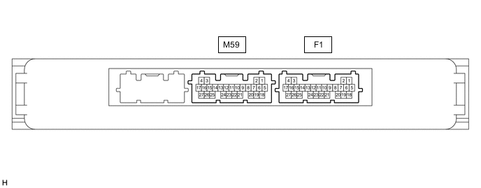
Disconnect the F1 certification ECU (smart key ECU assembly) connector.
-
Measure the voltage and resistance according to the value(s) in the table below.
Tech Tips
Measure the values on the wire harness side with the connector disconnected.
Terminal No. (Symbol) Wiring Color Terminal Description Condition Specified Condition F1-18 (E) - Body ground W-B - Body ground Ground Always Below 1 Ω F1-4 (+B) - Body ground GR - Body ground +B power supply Power switch off 11 to 14 V -
Reconnect the F1 certification ECU (smart key ECU assembly) connector.
-
Check for pulses according to the value(s) in the table below.
Terminal No. (Symbol) Wiring Color Terminal Description Condition Specified Condition F1-13 (LIN) - Body ground B - Body ground*1
L - Body ground*2
LIN communication line Power switch on (IG) Pulse generation
-
*1: for LHD
-
*2: for RHD
-
-
-
CHECK HYBRID VEHICLE CONTROL ECU
-
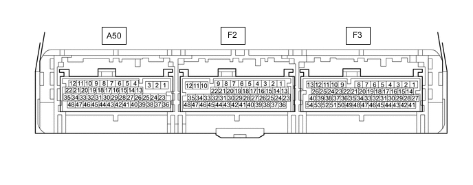
Disconnect the F2 and F3 hybrid vehicle control ECU connectors.
-
Measure the resistance and voltage according to the value(s) in the table below.
Terminal No. (Symbol) Wiring Color Terminal Description Condition Specified Condition F3-3 (E1) - Body ground W-B - Body ground Ground Always Below 1 Ω F2-34 (E12) - Body ground W-B - Body ground Ground Always Below 1 Ω F3-27 (BATT) - Body ground GR - Body ground Auxiliary battery power supply Power switch off 11 to 14 V -
Reconnect the F2 and F3 hybrid vehicle control ECU connectors.
-
Check for pulses according to the value(s) in the table below.
Terminal No. (Symbol) Wiring Color Terminal Description Condition Specified Condition F3-31 (LIN) - Body ground L - Body ground*1
BE - Body ground*2
LIN communication line Power switch on (IG) Pulse generation
-
*1: for LHD
-
*2: for RHD
-
-
-
CHECK ID CODE BOX (IMMOBILISER CODE ECU)

-
Disconnect the F19 ID code box (immobiliser code ECU) connector.
-
Measure the voltage and resistance according to the value(s) in the table below.
Tech Tips
Measure the values on the wire harness side with the connector disconnected.
Terminal No. (Symbol) Wiring Color Terminal Description Condition Specified Condition F19-5 (GND) - Body ground W - Body ground Ground Always Below 1 Ω F19-1 (+B) - Body ground W - Body ground*1
GR - Body ground*2
+B power supply Power switch off 11 to 14 V
-
*1: for LHD
-
*2: for RHD
-
-
Reconnect the F19 ID code box (immobiliser code ECU) connector.
-
Check for pulses according to the value(s) in the table below.
Terminal No. (Symbol) Wiring Color Terminal Description Condition Specified Condition F19-2 (LIN1) - Body ground V - Body ground LIN communication line Power switch on (IG) Pulse generation
-
-
CHECK DOUBLE LOCK DOOR CONTROL RELAY ASSEMBLY (w/ Double Locking System)

-
Disconnect the F15 double lock door control relay assembly connector.
-
Measure the voltage and resistance according to the value(s) in the table below.
Tech Tips
Measure the values on the wire harness side with the connector disconnected.
Terminal No. (Symbol) Wiring Color Terminal Description Condition Specified Condition F15-12 (+B) - Body ground R - Body ground Auxiliary battery power supply Power switch off 11 to 14 V F15-11 (CPUB) - Body ground P - Body ground Auxiliary battery power supply Power switch off 11 to 14 V F15-7 (GND) - Body ground LA - Body ground Ground Always Below 1 Ω -
Reconnect the F15 double lock door control relay assembly connector.
-
Check for pulses according to the value(s) in the table below.
Terminal No. (Symbol) Wiring Color Terminal Description Condition Specified Condition F15-9 (LIN) - Body ground GR - Body ground LIN communication line Double lock unset Pulse generation
-