CLEARANCE WARNING ECU REMOVAL

CAUTION / NOTICE / HINT
The necessary procedures (adjustment, calibration, initialization, or registration) that must be performed after parts are removed and installed, or replaced during clearance warning ECU assembly removal/installation are shown below.
| Replaced Part or Performed Procedure | Necessary Procedure | Effect/Inoperative Function when Necessary Procedure not Performed | Link |
|---|---|---|---|
| Disconnect cable from negative auxiliary battery terminal | Memorize steering angle neutral point | Lane departure alert system (w/ Steering Control) | |
| Intelligent clearance sonar system*1 | |||
| Simple intelligent parking assist system*1 | |||
| Pre-crash safety system | |||
| Parking assist monitor system | |||
| Initialize back door lock | Power door lock control system | ||
| Replacement of clearance warning ECU assembly |
|
|
*1: When performing learning using the GTS.
CAUTION:
Some of these service operations affect the SRS airbag system. Read the precautionary notices concerning the SRS airbag system before servicing.
PROCEDURE
-
REMOVE LOWER INSTRUMENT PANEL SUB-ASSEMBLY
-
REMOVE NO. 2 CLEARANCE WARNING BUZZER
-
REMOVE CLEARANCE WARNING ECU ASSEMBLY
-
for LHD:
-
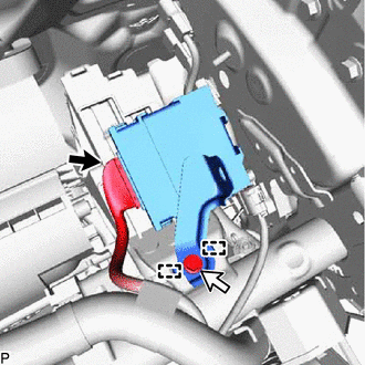
Disconnect the connector.
-
Remove the bolt.
-
Disengage the 2 guides to remove the clearance warning ECU assembly.
-
-
for RHD:
-
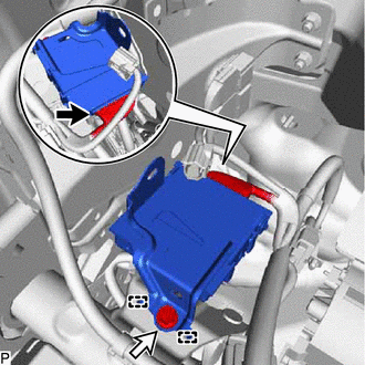
Disconnect the connector.
-
Remove the bolt.
-
Disengage the 2 guides to remove the clearance warning ECU assembly.
-
-