FRONT BUMPER DISASSEMBLY
PROCEDURE
-
REMOVE FRONT SIDE ULTRASONIC SENSOR (w/ TOYOTA Parking Assist-sensor System)
-
REMOVE ULTRASONIC SENSOR CLIP (w/ TOYOTA Parking Assist-sensor System)
-
REMOVE FRONT CORNER ULTRASONIC SENSOR (w/ TOYOTA Parking Assist-sensor System)
-
REMOVE FRONT CENTER ULTRASONIC SENSOR (w/ TOYOTA Parking Assist-sensor System)
-
REMOVE FRONT SIDE ULTRASONIC SENSOR RETAINER (w/ TOYOTA Parking Assist-sensor System)
-
REMOVE FRONT CORNER ULTRASONIC SENSOR RETAINER (w/ TOYOTA Parking Assist-sensor System)
-
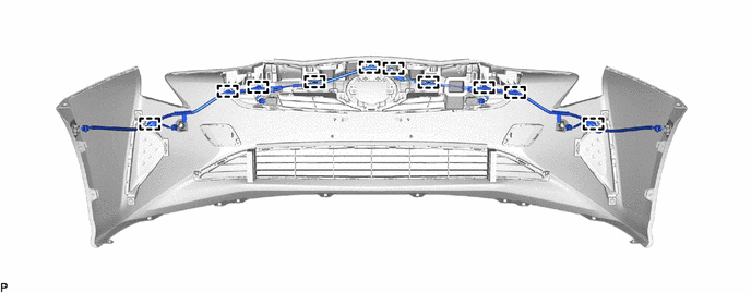
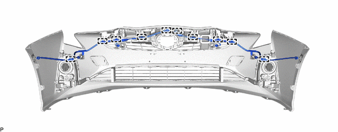
REMOVE NO. 3 ENGINE ROOM WIRE (w/ TOYOTA Parking Assist-sensor System)
-
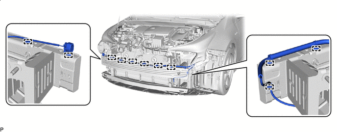
w/o Fog Light:
-
Disengage the 10 clamps and remove the No. 3 engine room wire.
-
-
w/ Fog Light:
-
Disengage the 10 clamps and remove the No. 3 engine room wire.
-
-
-
REMOVE MILLIMETER WAVE RADAR SENSOR ASSEMBLY (w/ Toyota Safety Sense)
-
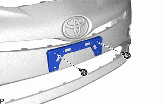
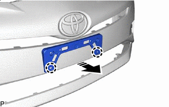
REMOVE FRONT BUMPER EXTENSION LH (w/o Fog Light)
-
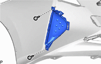
Remove the 2 screws.
-
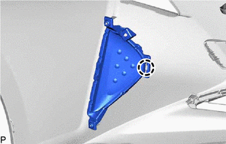
Disengage the claw to remove the front bumper extension LH.
-
-
REMOVE FRONT BUMPER EXTENSION RH (w/o Fog Light)
Tech Tips
Use the same procedure for the LH side.
-
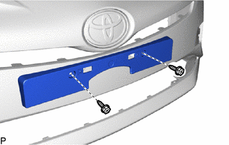
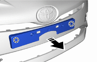
REMOVE FOG LIGHT ASSEMBLY LH (w/ Fog Light)
-
REMOVE FOG LIGHT ASSEMBLY RH (w/ Fog Light)
Tech Tips
Use the same procedure for the LH side.
-
REMOVE FRONT FENDER LINER RETAINER
-
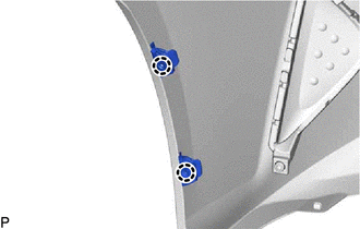
Disengage the 2 claws to remove the 2 front fender liner retainers.
Tech Tips
Use the same procedure for the RH side and LH side.
-
-
REMOVE HOOD TO FRONT END PANEL SEAL
-
Separate the double-sided tape and disengage the 2 clips to remove the hood to front end panel seal.
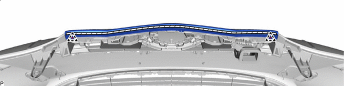

Double-sided Tape - -
-
-
REMOVE RADIATOR GRILLE SUB-ASSEMBLY
-
Remove the 2 screws and 4 clips.
-
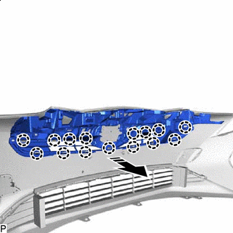

Remove in this Direction Disengage the 15 claws as shown in the illustration to remove the radiator grille sub-assembly.
-
-
REMOVE NO. 3 AIR CLEANER INLET
-
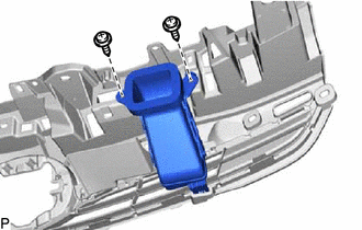
Remove the 2 screws.
-
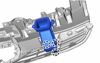
Disengage the 3 claws to remove the No. 3 air cleaner inlet.
-
-
REMOVE LOWER NO. 1 RADIATOR GRILLE
-
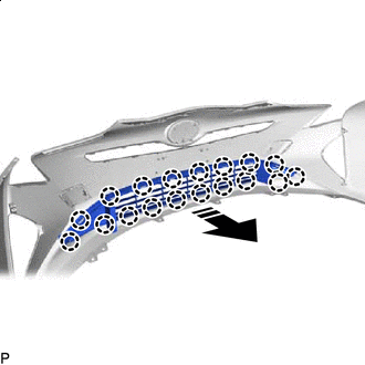
Remove in this Direction Disengage the 18 claws as shown in the illustration to remove the lower No. 1 radiator grille.
-
-
REMOVE FRONT BUMPER HOLE COVER LH
-
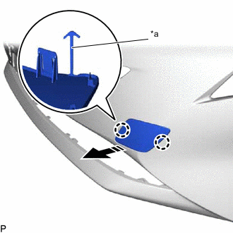
*a Hook Remove in this Direction Disengage the 2 claws as shown in the illustration.
-
Disengage the hook to remove the front bumper hole cover LH.
-
-
REMOVE FRONT BUMPER HOLE COVER RH
Tech Tips
Use the same procedure for the LH side.
-
REMOVE FRONT BUMPER EXTENSION MOUNTING BRACKET
-
for Extension Mounting Bracket Type A:
-
Remove the 2 screws.
-
Remove in this Direction Disengage the 2 claws and remove the front bumper extension mounting bracket as shown in the illustration.
-
-
for Extension Mounting Bracket Type B:
-
Remove the 2 screws.
-
Remove in this Direction Disengage the 2 claws and remove the front bumper extension mounting bracket as shown in the illustration.
-
-
-
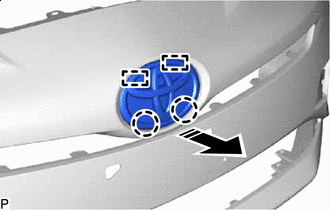
REMOVE RADIATOR GRILLE EMBLEM ASSEMBLY
-
Check if there are slits at the positions shown in the illustration.
Tech Tips
The removal procedure for the radiator grille emblem assembly will differ depending on the existence of slits.
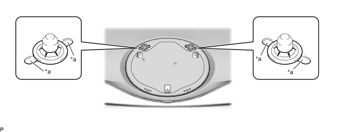
*a Slit - - -
w/ Slit:
-
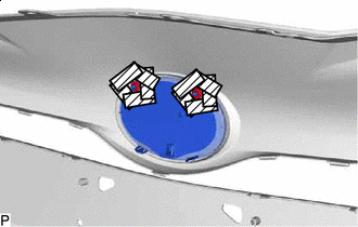
Protective Tape Apply protective tape around the spring nut.
-
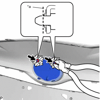
Using a plier nipper (side cutters), rotate the 2 spring nuts to align the cutouts of each spring nut as shown in the illustration.
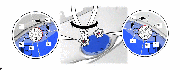
*a 90° *b Slit *c Cutout - - -
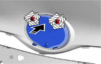
Using a plier nipper (side cutters), deform each spring nut as shown in the illustration and then remove the 2 spring nuts.
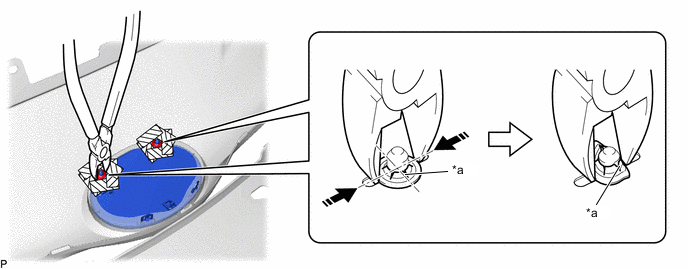
*a Cutout - - Pinch - - -
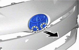
Remove in this Direction Disengage the 2 claws and 2 guides as shown in the illustration to remove the radiator grille emblem assembly.
-
-
w/o Slit (When Replacing the Radiator Grille Emblem Assembly):
-
Protective Tape Apply protective tape around the spring nut.
-
*a Cut Using a plier nipper (side cutters), cut the radiator grille emblem assembly at the positions shown in the illustration.
-
Push in this Direction Push the radiator grille emblem assembly to remove the 2 spring nuts as shown in the illustration.
CAUTION:
Make sure to cover the spring nuts with a piece of cloth or equivalent to prevent them from flying off during removal.
-
Remove in this Direction Disengage the 2 claws as shown in the illustration to remove the radiator grille emblem assembly.
-
-
w/o Slit (When Replacing the Front Bumper Cover):
-
Using a center punch, make a depression at the positions shown in the illustration.
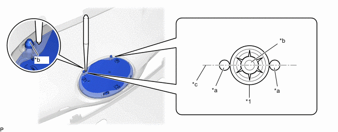
*1 Spring Nut - - *a Depression *b Pin of Radiator Grille Emblem Assembly *c Center Line - - Tech Tips
-
Make sure to make the depressions so they are aligned with the center line of the pin of the radiator grille emblem assembly.
-
Make sure to make the depressions correctly so that a plier nipper (side cutters) can be used to pinch the spring nuts.
-
-
Using a plier nipper (side cutters), rotate the 2 spring nuts to align the cutouts of each spring nut as shown in the illustration.
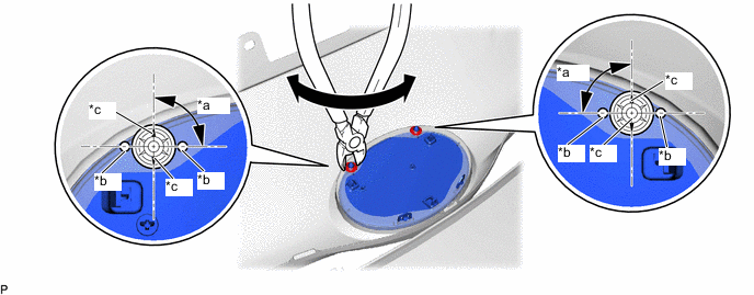
*a 90° *b Depression *c Cutout - - -
Using a plier nipper (side cutters), deform each spring nut as shown in the illustration and then remove the 2 spring nuts.
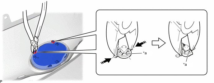
*a Cutout - - Pinch - - -
Remove in this Direction Disengage the 2 claws and 2 guides as shown in the illustration to remove the radiator grille emblem assembly.
-
-
-
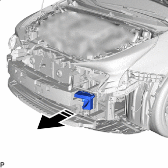
REMOVE FRONT BUMPER ENERGY ABSORBER (for Type A)
-
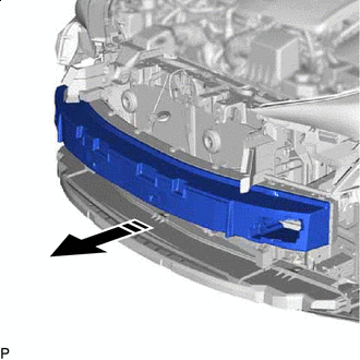
Remove in this Direction Remove the front bumper energy absorber as shown in the illustration.
-
-
REMOVE FRONT ENERGY ABSORBER MOUNTING REINFORCEMENT LH (for Type B)
-
Remove in this Direction Remove the front energy absorber mounting reinforcement LH as shown in the illustration.
-
-
REMOVE FRONT ENERGY ABSORBER MOUNTING REINFORCEMENT RH (for Type B)
Tech Tips
Use the same procedure for the LH side.
-
REMOVE FRONT BUMPER ENERGY ABSORBER (for Type B)
-
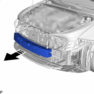
Remove in this Direction Remove the front bumper energy absorber as shown in the illustration.
-
-
REMOVE LOWER FRONT BUMPER ABSORBER
-
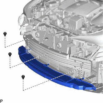
Remove the 3 clips and lower front bumper absorber.
-
-
REMOVE RADIATOR SHUTTER SUB-ASSEMBLY (for Type A)
-
REMOVE RADIATOR SHUTTER SUB-ASSEMBLY (for Type B)
-
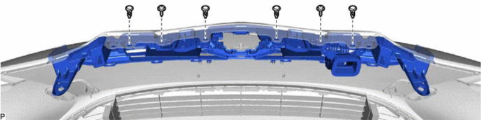
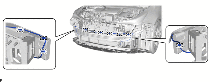
REMOVE FRONT BUMPER REINFORCEMENT SUB-ASSEMBLY (for Type A)
-
Disengage the 10 clamps.
-
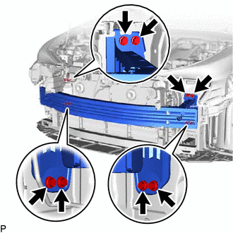
Remove the 8 bolts.
-
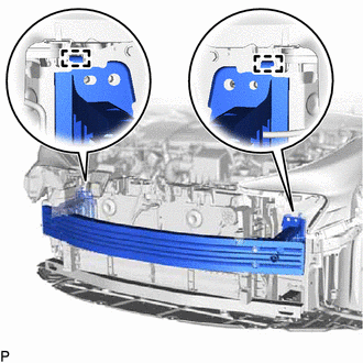
Disengage the 2 guides to remove the front bumper reinforcement sub-assembly.
-
-
REMOVE FRONT BUMPER REINFORCEMENT SUB-ASSEMBLY (for Type B)
-
Disengage the 11 clamps.
-
Remove the 8 bolts.
-
Disengage the 2 guides to remove the front bumper reinforcement sub-assembly.
-
-
REMOVE NO. 2 FRONT BUMPER REINFORCEMENT
-
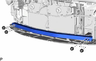
Remove the 4 nuts and No. 2 front bumper reinforcement.
-
-
REMOVE FRONT BUMPER EXTENSION LH
-
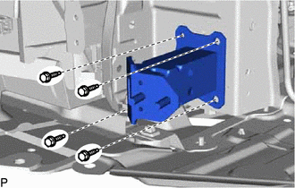
Remove the 4 bolts and front bumper extension LH.
-
-
REMOVE FRONT BUMPER EXTENSION RH
Tech Tips
Use the same procedure for the LH side.
-
REMOVE FRONT BUMPER SIDE SUPPORT LH
-
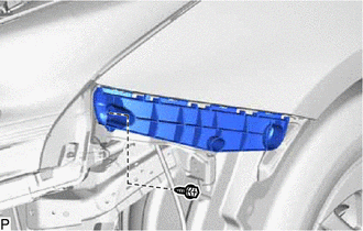
Remove the bolt.
-
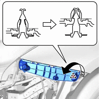
Remove in this Direction Disengage the clip as shown in the illustration.
-
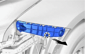
Remove in this Direction Disengage the claw as shown in the illustration to remove the front bumper side support LH.
-
-
REMOVE FRONT BUMPER SIDE SUPPORT RH
Tech Tips
Use the same procedure for the LH side.