VEHICLE PROXIMITY NOTIFICATION SYSTEM Sound does not Turn OFF when the Vehicle Approaching Speaker Switch is Pressed
DESCRIPTION
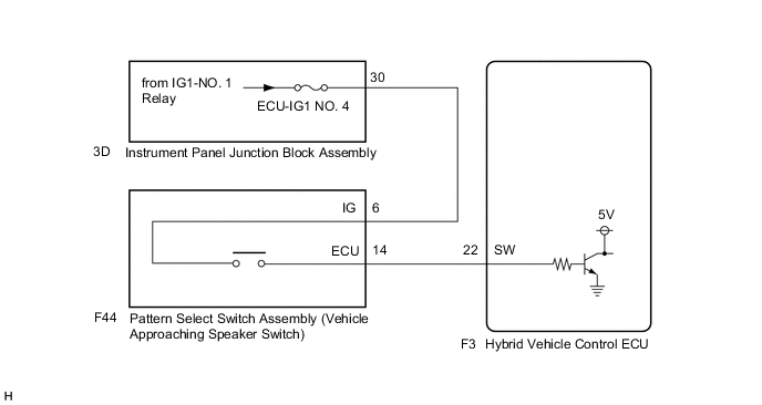
When the pattern select switch assembly (vehicle approaching speaker switch) is pushed when the vehicle approaching speaker system is on, the hybrid vehicle control ECU receives a signal to temporarily suspend output of the warning sound from the vehicle approaching speaker assembly.
WIRING DIAGRAM
CAUTION / NOTICE / HINT
Note
Inspect the fuses of circuits related to this system before performing the following procedure.
PROCEDURE
-
READ VALUE USING GTS (Operation Cancel SW)
-
Turn the power switch off.
-
Connect the GTS to the DLC3.
-
Turn the power switch on (IG).
-
Turn the GTS on.
-
Enter the following menus: Body Electrical / Vehicle Proximity Notification System / Data List.
-
Read the Data List according to the display on the GTS.
Body Electrical > Vehicle Proximity Notification System > Data ListTester Display Measurement Item Range Normal Condition Diagnostic Note Operation Cancel SW Pattern select switch assembly (vehicle approaching speaker switch) signal OFF or ON OFF: Pattern select switch assembly (vehicle approaching speaker switch) is not pressed.
ON: Pattern select switch assembly (vehicle approaching speaker switch) is pressed.
-
Body Electrical > Vehicle Proximity Notification System > Data ListTester Display Operation Cancel SW Result Result Proceed to The GTS display changes according to the operation of the vehicle approaching speaker switch A The GTS display does not change according to the operation of the vehicle approaching speaker switch B
A 
REPLACE HYBRID VEHICLE CONTROL ECU Click here
B 
-
-
INSPECT PATTERN SELECT SWITCH ASSEMBLY (VEHICLE APPROACHING SPEAKER SWITCH)
-
Remove the pattern select switch assembly (vehicle approaching speaker switch).
-
Inspect the pattern select switch assembly (vehicle approaching speaker switch).
Result Proceed to OK NG
NG
REPLACE PATTERN SELECT SWITCH ASSEMBLY (VEHICLE APPROACHING SPEAKER SWITCH) Click here
OK
-
-
CHECK HARNESS AND CONNECTOR (PATTERN SELECT SWITCH ASSEMBLY (VEHICLE APPROACHING SPEAKER SWITCH) - IG POWER SOURCE)
-
Measure the voltage according to the value(s) in the table below.
Standard Voltage Tester Connection Condition Specified Condition F44-6 (IG) - Body ground Power switch on (IG) 11 to 14 V Power switch off Below 1 V Result Proceed to OK NG
NG 
CHECK HARNESS AND CONNECTOR (PATTERN SELECT SWITCH ASSEMBLY (VEHICLE APPROACHING SPEAKER SWITCH) - INSTRUMENT PANEL JUNCTION BLOCK ASSEMBLY) Click here
OK
-
-
CHECK HARNESS AND CONNECTOR (HYBRID VEHICLE CONTROL ECU - PATTERN SELECT SWITCH ASSEMBLY (VEHICLE APPROACHING SPEAKER SWITCH))
-
Disconnect the F3 hybrid vehicle control ECU connector.
-
Measure the resistance according to the value(s) in the table below.
Standard Resistance Tester Connection Condition Specified Condition F3-22 (SW) - F44-14 (ECU) Always Below 1 Ω F3-22 (SW) or F44-14 (ECU) - Body ground Always 10 kΩ or higher Result Proceed to OK NG
OK
REPLACE HYBRID VEHICLE CONTROL ECU Click here
NG
REPAIR OR REPLACE HARNESS OR CONNECTOR
-
-
CHECK HARNESS AND CONNECTOR (PATTERN SELECT SWITCH ASSEMBLY (VEHICLE APPROACHING SPEAKER SWITCH) - INSTRUMENT PANEL JUNCTION BLOCK ASSEMBLY)
-
Disconnect the 3D instrument panel junction block assembly connector.
-
Measure the voltage according to the value(s) in the table below.
Standard Voltage Tester Connection Condition Specified Condition F44-6 (IG) - 3D-30 Always Below 1 Ω F44-6 (IG) or 3D-30 - Body ground Always 10 kΩ or higher Result Proceed to OK NG
OK
REPLACE INSTRUMENT PANEL JUNCTION BLOCK ASSEMBLY Click here
NG
REPAIR OR REPLACE HARNESS OR CONNECTOR
-