PARKING BRAKE CABLE(for Rear Side) INSTALLATION
CAUTION / NOTICE / HINT
Tech Tips
Use the same procedure for the No. 2 parking brake cable assembly and No. 3 parking brake cable assembly.
PROCEDURE
-
INSTALL NO. 3 PARKING BRAKE CABLE ASSEMBLY
-
Insert the No. 3 parking brake cable assembly into the vehicle body.
-
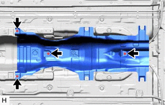
Install the No. 3 parking brake cable assembly with the 4 bolts and nut.
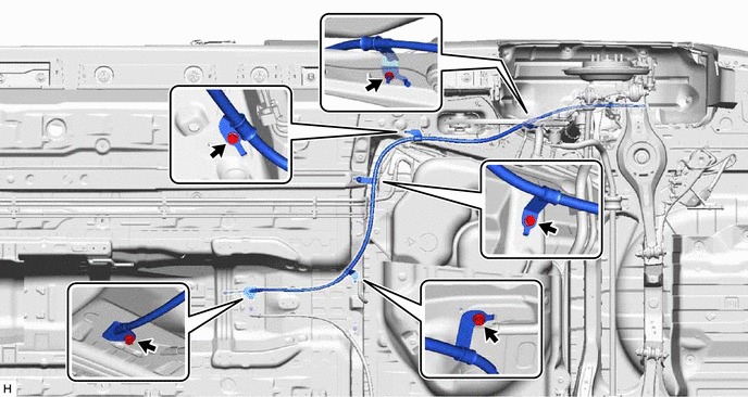
- Torque:
- Bolt
- 6.0 N*m { 61 kgf*cm, 53 in.*lbf }
- Nut
- 15.5 N*m { 158 kgf*cm, 11 ft.*lbf }
-
w/ Clip:
-
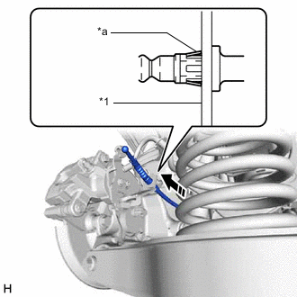
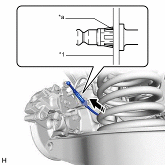
*1 Rear Disc Brake Cylinder Assembly *a Clip Engage the clip to install the No. 3 parking brake cable assembly to the rear disc brake cylinder assembly.
Note
Be sure to engage the clip to the rear disc brake cylinder assembly as shown in the illustration.
-
*a Clip 
Upper Side Connect the No. 3 parking brake cable assembly to the rear disc brake cylinder assembly.
Note
-
Do not remove the clip from the No. 3 parking brake cable assembly.
-
If the clip is removed from the No. 3 parking brake cable assembly, make sure to replace it with a new one.
-
When engaging the clip, make sure that the open end of the clip is facing upward.
-
-
-
w/o Clip:
-
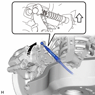
*1 Rear Disc Brake Cylinder Assembly *a Clip Engage the clip to install the No. 3 parking brake cable assembly to the rear disc brake cylinder assembly.
Note
Be sure to engage the clip to the rear disc brake cylinder assembly as shown in the illustration.
-
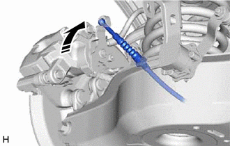
Connect the No. 3 parking brake cable assembly to the rear disc brake cylinder assembly.
-
-
-
INSTALL PARKING BRAKE LEVER PROTECTOR
-
Install the parking brake lever protector to the No. 3 parking brake cable assembly.
-
-
INSTALL REAR FLOOR SIDE MEMBER COVER LH (for LH Side)
w/ Canister Pump Module:
w/o Canister Pump Module:
-
INSTALL NO. 1 FLOOR UNDER COVER ASSEMBLY (for RH Side)
w/ Canister Pump Module:
w/o Canister Pump Module:
-
INSTALL FRONT NO. 2 FLOOR HEAT INSULATOR
-
Install the front No. 2 floor heat insulator with the 4 nuts.
- Torque:
- 5.0 N*m { 51 kgf*cm, 44 in.*lbf }
-
-
INSTALL FRONT EXHAUST PIPE ASSEMBLY (TWC: Rear Catalyst)
-
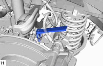
CONNECT NO. 1 PARKING BRAKE PULL ROD SUB-ASSEMBLY
-
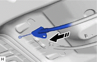
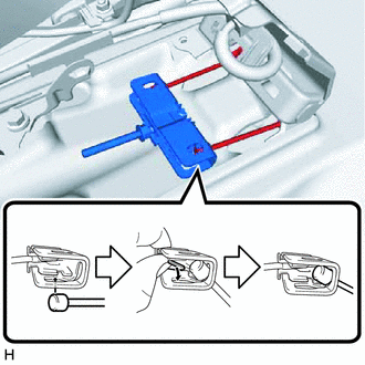
Connect the No. 1 parking brake pull rod sub-assembly to the No. 3 parking brake cable assembly as shown in the illustration.
-
-
CONNECT NO. 1 PARKING BRAKE CABLE ASSEMBLY
-
INSTALL REAR CONSOLE BOX ASSEMBLY
-
INSPECT PARKING BRAKE PEDAL TRAVEL
-
ADJUST PARKING BRAKE PEDAL TRAVEL