REAR DISC BRAKE PAD REPLACEMENT

CAUTION / NOTICE / HINT
The necessary procedures (adjustment, calibration, initialization, or registration) that must be performed after parts are removed and installed, or replaced during rear disc brake pad removal/installation are shown below.
| Replaced Part or Performed Procedure | Necessary Procedure | Effect/Inoperative Function when Necessary Procedure not Performed | Link |
|---|---|---|---|
| Auxiliary battery terminal is disconnected/reconnected | Memorize steering angle neutral point | Lane departure alert system (w/ Steering Control) | |
| Intelligent clearance sonar system | |||
| Simple intelligent parking assist system | |||
| Pre-crash safety system | |||
| Parking assist monitor system | |||
| Initialize back door lock | Power door lock control system |
Note
-
Immediately after installing the brake pads, the braking performance may be reduced. Always perform a road test in a safe place while paying attention to the surroundings.
-
After replacing the rear disc brake pads, the brake pedal may feel soft due to clearance between the rear disc brake pads and rear disc. Depress the brake pedal several times until the brake pedal feels firm.
-
When the brake pedal is first depressed after replacing the brake pads or pushing back the disc brake piston, DTC C1214 may be stored. As there is no malfunction, clear the DTC.
-
While the auxiliary battery is connected, even if the power switch is off, the brake control system activates when the brake pedal is depressed or any door courtesy switch turns on. Therefore, when servicing the brake system components, do not operate the brake pedal or open/close the doors while the auxiliary battery is connected.
-
After replacing the rear disc brake pads, always perform a road test to check the braking performance and check for vibrations.
Tech Tips
-
Use the same procedure for the RH side and LH side.
-
The following procedure is for the LH side.
PROCEDURE
-
PRECAUTION
Note
After turning the power switch off, waiting time may be required before disconnecting the cable from the negative (-) auxiliary battery terminal. Therefore, make sure to read the disconnecting the cable from the negative (-) auxiliary battery terminal notices before proceeding with work.
-
DISABLE BRAKE CONTROL
-
REMOVE REAR WHEEL
-
LOOSEN NO. 1 WIRE ADJUSTING NUT
for LHD: Click here
for RHD: Click here
-
REMOVE PARKING BRAKE LEVER PROTECTOR
-
SEPARATE NO. 3 PARKING BRAKE CABLE ASSEMBLY
-
SEPARATE REAR DISC BRAKE CYLINDER ASSEMBLY
CAUTION:
Be careful not to get pinched by the rear disc brake cylinder assembly or other parts when removing the rear disc brake pads.
-
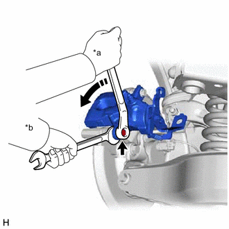
*a Turn *b Hold Hold the rear disc brake pad guide pins and remove the bolt.
-
Pull the rear disc brake cylinder assembly upward.
-
-
REMOVE ANTI SQUEAL SPRING
-
REMOVE REAR DISC BRAKE PAD KIT
-
Remove the 2 rear disc brake pads from the rear disc brake cylinder mounting.
-
-
REMOVE REAR DISC BRAKE ANTI SQUEAL SHIM KIT
-
INSTALL REAR DISC BRAKE ANTI SQUEAL SHIM KIT
-
INSTALL REAR DISC BRAKE PAD KIT
CAUTION:
Be careful not to get pinched by the rear disc brake cylinder assembly or other parts when installing the rear disc brake pads.
-
Install the 2 rear disc brake pads to the rear disc brake cylinder mounting.
Note
There should be no oil or grease on the friction surfaces of the disc brake pads or the rear disc.
-
-
INSTALL ANTI SQUEAL SPRING
-
INSTALL REAR DISC BRAKE CYLINDER ASSEMBLY
-
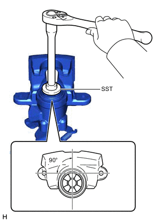
To compensate for pad lining thickness, use SST to adjust the protrusion of the rear disc brake piston by turning it.
- SST
- 09719-12010 ( 09719-01030 )
Note
-
Place the disc between the 2 brake pads and determine the piston return value.
-
Turn the rear disc brake piston to the position where the protrusion on the rear disc brake pad lines up properly with the piston groove.
-
Make sure the brake fluid does not overflow from the reservoir.
-
Hold the rear disc brake pad guide pin and install the rear disc brake cylinder assembly to the rear disc brake cylinder mounting with the bolt.
- Torque:
- 34.3 N*m { 350 kgf*cm, 25 ft.*lbf }
Note
-
Install the rear disc brake cylinder assembly while holding both of the rear disc brake pads because the anti-squeal springs may fall off the rear disc brake pads.
-
Be sure that the anti-squeal springs are installed to the rear disc brake pads.
-
-
CONNECT NO. 3 PARKING BRAKE CABLE ASSEMBLY
-
INSTALL PARKING BRAKE LEVER PROTECTOR
-
CONNECT CABLE TO NEGATIVE AUXILIARY BATTERY TERMINAL
-
Connect the reservoir level switch connector.
-
Connect the cable to the negative (-) auxiliary battery terminal.
-
Turn the power switch on (READY).
-
Depress the brake pedal and release it.
-
Clear the DTCs.
-
-
INSPECT BRAKE FLUID LEVEL IN RESERVOIR
-
ADJUST PARKING BRAKE
-
INSTALL REAR WHEEL