BRAKE BOOSTER PUMP(for LHD) REMOVAL
CAUTION / NOTICE / HINT
The necessary procedures (adjustment, calibration, initialization, or registration) that must be performed after parts are removed, installed, or replaced during brake booster pump assembly removal/installation are shown below.
| Replaced Part or Performed Procedure | Necessary Procedure | Effect/Inoperative Function when Necessary Procedure not Performed | Link |
|---|---|---|---|
| Auxiliary battery terminal is disconnected/reconnected | Memorize steering angle neutral point | Lane departure alert system (w/ Steering Control) | |
| Intelligent clearance sonar system | |||
| Simple intelligent parking assist system | |||
| Pre-crash safety system | |||
| Parking assist monitor system | |||
| Initialize back door lock | Power door lock control system |
CAUTION / NOTICE / HINT
Note
While the auxiliary battery is connected, even if the power switch is off, the brake control system activates when the brake pedal is depressed or any door courtesy switch turns on. Therefore, when servicing the brake system components, do not operate the brake pedal or open/close the doors while the auxiliary battery is connected.
PROCEDURE
-
REMOVE BRAKE ACTUATOR ASSEMBLY
-
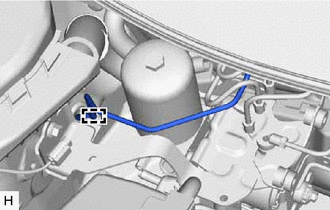
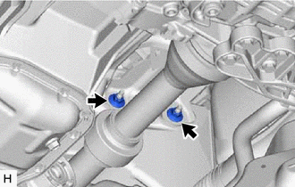
SEPARATE NO. 1 BRAKE ACTUATOR TUBE
-
Remove the 2 nuts and separate the No. 1 brake actuator tube.
-
-
REMOVE ACCUMULATOR TO BRAKE MASTER CYLINDER TUBE
-
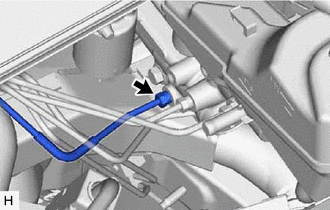
Using a union nut wrench, disconnect the accumulator to brake master cylinder tube from the brake booster with master cylinder assembly.
-
Disengage the claw to separate the clamp cover.
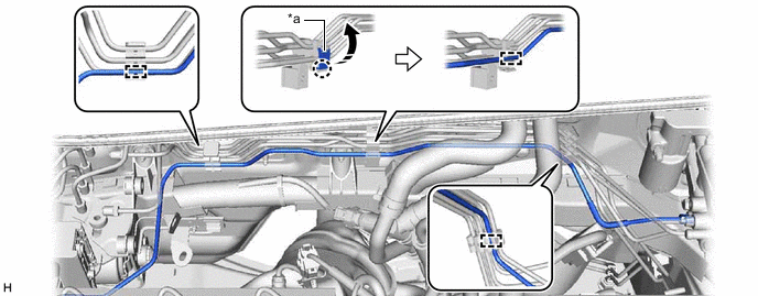
*a Clamp Cover - - -
Disengage the 3 clamps and remove the accumulator to brake master cylinder tube.
-
-
REMOVE BRAKE BOOSTER PUMP ASSEMBLY
-
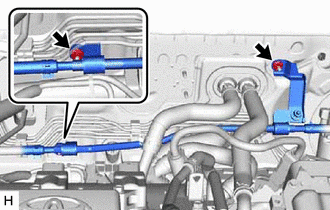
Disengage the clamp to separate the No. 3 front brake tube from the brake actuator bracket assembly.
-
Remove the 2 nuts.
-
Remove the bolt of the brake actuator bracket assembly.
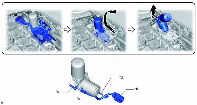
*a Union *b Connector *c Wire Harness *d Stud 
Remove in this Direction - - -
Remove the brake booster pump assembly as shown in the illustration.
Note
-
Do not apply excessive force to the brake lines or refrigerant lines.
-
Do not carry the brake booster pump assembly by the parts shown in the illustration.
-
Do not drop the brake booster pump assembly when carrying it.
-
Be careful not to allow brake fluid to enter the connector.
Tech Tips
Move the brake actuator bracket assembly as necessary to allow the brake booster pump assembly to be removed.
-
-
Remove the brake actuator bracket assembly from the vehicle body.
Note
Do not apply excessive force to the brake lines or refrigerant lines.
-
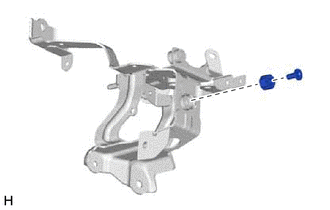
Remove the brake actuator case collar and brake booster pump bushing from the brake actuator bracket assembly.
-
-
REMOVE NO. 1 BRAKE ACTUATOR HOSE
-
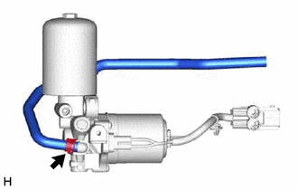
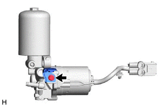
Slide the clip and remove the No. 1 brake actuator hose from the brake booster pump assembly.
-
-
REMOVE NO. 1 BRAKE TUBE CLAMP BRACKET
-
Remove the bolt and No. 1 brake tube clamp bracket from the brake booster pump assembly.
-