BRAKE SYSTEM ON-VEHICLE INSPECTION

CAUTION / NOTICE / HINT
Note
DTCs may be stored during the inspection procedure. Be sure to clear the DTCs and check that no DTCs are output after the inspection is finished.
PROCEDURE
-
INSPECT PRESSURE SENSOR
-
Check auxiliary battery voltage.
Standard Voltage Tester Connection Condition Specified Condition Auxiliary battery Power switch off 11 to 14 V -
Set a pedal effort gauge, SST and connect the GTS.
-
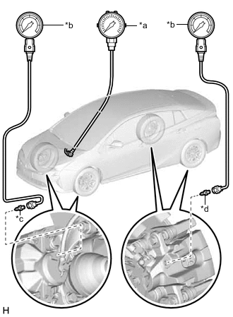
*a Pedal Effort Gauge *b SST (LSPV Gauge) *c SST (No. 1 Nipple) *d SST (No. 3 Nipple) Set a pedal effort gauge and SST.
- SST
- 09709-29018 ( 09709-00060, 09709-00080 )
-
Connect the GTS to the DLC3 with the power switch off, park (P) selected and parking brake applied.
-
Turn the power switch on (IG) and turn the GTS on.
-
Bleed air from SST (LSPV gauge).
Tech Tips
-
-
Inspect the reaction force pressure and servo pressure.
-
Enter the following menus: Chassis / ABS/VSC/TRC / Data List / Reaction Force Pressure and Servo Pressure.
Chassis > ABS/VSC/TRC > Data ListTester Display Reaction Force Pressure Servo Pressure -
Check the value output from "Reaction Force Pressure" and "Servo Pressure" by depressing the brake pedal.
Standard Result Pedal Effort Reaction Force Pressure
(MPa)
Servo Pressure
(MPa)
Front Right Wheel Hydraulic Pressure Rear Left Wheel Hydraulic Pressure 50 N (5 kgf, 11.2 lbf) 0.08 to 0.88 1.5 to 5.5 1.2 to 5.2 MPa (12.2 to 53.0 kgf/cm2, 174 to 754 psi)
1.2 to 5.2 MPa (12.2 to 53.0 kgf/cm2, 174 to 754 psi)
100 N (10 kgf, 22.5 lbf) 0.74 to 1.54 5.8 to 9.8 5.5 to 9.5 MPa (56.1 to 96.9 kgf/cm2, 798 to 1378 psi)
5.5 to 9.5 MPa (56.1 to 96.9 kgf/cm2, 798 to 1378 psi)
150 N (15 kgf, 33.7 lbf) 1.40 to 2.20 6.9 to 10.9 6.6 to 10.6 MPa (67.3 to 108.1 kgf/cm2, 957 to 1537 psi)
6.6 to 10.6 MPa (67.3 to 108.1 kgf/cm2, 957 to 1537 psi)
200 N (20 kgf, 45.0 lbf) 2.06 to 2.86 6.9 to 10.9 6.6 to 10.6 MPa (67.3 to 108.1 kgf/cm2, 957 to 1537 psi)
6.6 to 10.6 MPa (67.3 to 108.1 kgf/cm2, 957 to 1537 psi)
Standard Result Pedal Effort Reaction Force Pressure
(MPa)
Servo Pressure
(MPa)
Front Left Wheel Hydraulic Pressure Rear Right Wheel Hydraulic Pressure 50 N (5 kgf, 11.2 lbf) 0.08 to 0.88 1.5 to 5.5 1.2 to 5.2 MPa (12.2 to 53.0 kgf/cm2, 174 to 754 psi)
1.2 to 5.2 MPa (12.2 to 53.0 kgf/cm2, 174 to 754 psi)
100 N (10 kgf, 22.5 lbf) 0.74 to 1.54 5.8 to 9.8 5.5 to 9.5 MPa (56.1 to 96.9 kgf/cm2, 798 to 1378 psi)
5.5 to 9.5 MPa (56.1 to 96.9 kgf/cm2, 798 to 1378 psi)
150 N (15 kgf, 33.7 lbf) 1.40 to 2.20 6.9 to 10.9 6.6 to 10.6 MPa (67.3 to 108.1 kgf/cm2, 957 to 1537 psi)
6.6 to 10.6 MPa (67.3 to 108.1 kgf/cm2, 957 to 1537 psi)
200 N (20 kgf, 45.0 lbf) 2.06 to 2.86 6.9 to 10.9 6.6 to 10.6 MPa (67.3 to 108.1 kgf/cm2, 957 to 1537 psi)
6.6 to 10.6 MPa (67.3 to 108.1 kgf/cm2, 957 to 1537 psi)
-
-
Remove the pedal effort gauge and SST.
-
Remove the pedal effort gauge and SST, and bleed the brake line.
Tech Tips
-
-
Inspect the accumulator pressure.
-
Enter the following menus: Chassis / ABS/VSC/TRC / Data List / Accumulator Pressure and MT Voltage Value.
Chassis > ABS/VSC/TRC > Data ListTester Display MT Voltage Value Accumulator Pressure -
While fully depressing the brake pedal 4 or 5 times, check that the MT voltage value is 10 V or more once or more.
Tech Tips
Usually the MT voltage value is 0 V.
-
After confirming that the booster pump motor stops, check the accumulator pressure.
Standard Result Specified Condition 15 to 21 MPa
-
-
-
INSPECT BRAKE BOOSTER WITH MASTER CYLINDER ASSEMBLY
-
Check auxiliary battery voltage.
Standard Voltage Tester Connection Condition Specified Condition Auxiliary battery Power switch off 11 to 14 V -
Set a pedal effort gauge, SST and connect the GTS.
-
*a Pedal Effort Gauge *b SST (LSPV Gauge) *c SST (No. 1 Nipple) *d SST (No. 3 Nipple) Set a pedal effort gauge and SST.
- SST
- 09709-29018 ( 09709-00060, 09709-00080 )
-
Connect the GTS to the DLC3 with the power switch off, park (P) selected and parking brake applied.
-
Turn the power switch on (IG) and turn the GTS on.
-
Clear the DTCs.
Chassis > ABS/VSC/TRC > Clear DTCs -
Bleed air from SST (LSPV gauge).
Tech Tips
-
-
Check operation without the brake booster.
-
Inspect and adjust the brake pedal height.
-
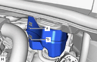
*a Fluid Level Support Line *b MIN Line Adjust the brake fluid level in the reservoir between MIN line and fluid level support line.
-
Turn the GTS on and enter the following menus: Chassis / ABS/VSC/TRC / Utility / ECB (Electronically Controlled Brake system) Utility.
Chassis > ABS/VSC/TRC > UtilityTester Display ECB Utility -
Select "Motor Invalid" on the "ECB (Electronically Controlled Brake system) Utility" screen.
-
Perform "Motor Invalid" according to the display on the GTS.
-
Depress the brake pedal 40 times or more to return all the fluid in the accumulator back to the reservoir.
Tech Tips
A buzzer may sound due to low accumulator pressure. As this is not a malfunction, continue the procedure.
-
Check that the brake pedal is firm.
-
Enter the following menus: Chassis / ABS/VSC/TRC / Data List / Stroke Sensor and Stroke Sensor 2.
Chassis > ABS/VSC/TRC > Data ListTester Display Stroke Sensor Stroke Sensor2 -
Check the values output from "Stroke Sensor" and "Stroke Sensor 2" by depressing the brake pedal.
Standard Result Pedal Effort Stroke Sensor
(V)
Stroke Sensor 2
(V)
Front Right Wheel Hydraulic Pressure Rear Left Wheel Hydraulic Pressure 200 N (20 kgf, 45.0 lbf) 1.14 to 1.84 3.14 to 3.86 0.03 to 2.03 MPa (0.3 to 20.7 kgf/cm2, 4.4 to 294 psi)
0.03 to 2.03 MPa (0.3 to 20.7 kgf/cm2, 4.4 to 294 psi)
500 N (51 kgf, 112.4 lbf) 1.31 to 2.01 2.99 to 3.69 2.00 to 4.00 MPa (20.4 to 40.8 kgf/cm2, 290 to 580 psi)
2.00 to 4.00 MPa (20.4 to 40.8 kgf/cm2, 290 to 580 psi)
Standard Result Pedal Effort Stroke Sensor
(V)
Stroke Sensor 2
(V)
Front Left Wheel Hydraulic Pressure Rear Right Wheel Hydraulic Pressure 200 N (20 kgf, 45.0 lbf) 1.14 to 1.84 3.14 to 3.86 0.03 to 2.03 MPa (0.3 to 20.7 kgf/cm2, 4.4 to 294 psi)
0.03 to 2.03 MPa (0.3 to 20.7 kgf/cm2, 4.4 to 294 psi)
500 N (51 kgf, 112.4 lbf) 1.31 to 2.01 2.99 to 3.69 2.00 to 4.00 MPa (20.4 to 40.8 kgf/cm2, 290 to 580 psi)
2.00 to 4.00 MPa (20.4 to 40.8 kgf/cm2, 290 to 580 psi)
-
Remove the pedal effort gauge and SST, and bleed the brake system.
Tech Tips
-
Enter the following menus: Chassis / ABS/VSC/TRC / Data List / Accumulator Pressure, and check the output pressure.
Chassis > ABS/VSC/TRC > Data ListTester Display Accumulator Pressure Standard Result Specified Condition 15 to 21 MPa -
Clear the DTCs.
Chassis > ABS/VSC/TRC > Clear DTCs
-
-
-
INSPECT STROKE SIMULATOR
-
Check auxiliary battery voltage.
Standard Voltage Tester Connection Condition Specified Condition Auxiliary battery Power switch off 11 to 14 V -
Connect the GTS and set a pedal effort gauge.
-
Set a pedal effort gauge.
-
Connect the GTS to the DLC3 with the power switch off, park (P) selected and parking brake applied.
-
Turn the power switch on (IG) and turn the GTS on.
-
Clear the DTCs.
Chassis > ABS/VSC/TRC > Clear DTCs
-
-
Check operation with the brake booster.
-
Turn the power switch on (IG).
-
Enter the following menus: Chassis / ABS/VSC/TRC / Data List / Stroke Sensor and Stroke Sensor 2.
Chassis > ABS/VSC/TRC > Data ListTester Display Stroke Sensor Stroke Sensor2 -
Depress the brake pedal 4 or 5 times.
-
Check the values output from "Stroke Sensor" and "Stroke Sensor 2" by depressing the brake pedal.
Standard Voltage Pedal Effort Stroke Sensor
(V)
Stroke Sensor 2
(V)
50 N (5 kgf, 11.2 lbf) 1.05 to 1.75 3.25 to 3.95 100 N (10 kgf, 22.5 lbf) 1.18 to 1.88 3.12 to 3.82 150 N (15 kgf, 33.7 lbf) 1.28 to 1.98 3.02 to 3.72
-
-