ELECTRONICALLY CONTROLLED BRAKE SYSTEM, Diagnostic DTC:C1425
| DTC Code | DTC Name |
|---|---|
| C1425 | Open in Stop Switch Circuit |
DESCRIPTION
The skid control ECU (brake booster with master cylinder assembly) detects the brake operating conditions through a signal transmitted by the stop light switch assembly.
The skid control ECU incorporates a circuit to detect an open circuit. This DTC is output when an open circuit is detected in the stop light signal input line.
| DTC No. | Detection Item | INF Code | DTC Detection Condition | Trouble Area | Note |
|---|---|---|---|---|---|
| C1425 | Open in Stop Switch Circuit | 231 | An open stop light switch circuit continues for 10 seconds or more. |
|
Electronically controlled brake system DTC |
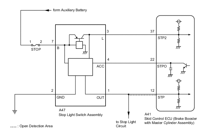
WIRING DIAGRAM
Figure 1. w/ Canister Pump Module:
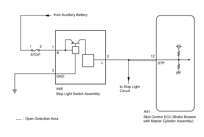
Figure 2. w/o Canister Pump Module:
CAUTION / NOTICE / HINT
Note
-
After replacing the skid control ECU (brake booster with master cylinder assembly), perform linear solenoid valve offset learning, ABS holding solenoid valve learning, yaw rate and acceleration sensor zero point calibration and system information memorization after performing "Reset Memory".
-
Inspect the fuses for circuits related to this system before performing the following procedure.
PROCEDURE
-
CHECK STOP LIGHT OPERATION
-
Check that the stop lights come on when the brake pedal is depressed and go off when the brake pedal is released.
OK Condition Illumination Condition Brake pedal depressed. On Brake pedal released. Off Result Proceed to OK NG
NG 
INSPECT STOP LIGHT SWITCH ASSEMBLY Click here
OK 
-
-
READ VALUE USING GTS (STOP LIGHT SWITCH ASSEMBLY)
-
Select the Data List on the GTS.
Chassis > ABS/VSC/TRC > Data ListTester Display Measurement Item Range Normal Condition Diagnostic Note Stop Light SW Stop light switch assembly ON or OFF ON: Brake pedal depressed
OFF: Brake pedal released
-
Chassis > ABS/VSC/TRC > Data ListTester Display Stop Light SW -
Check the value of Stop Light SW when the brake pedal is not depressed.
Result Result Proceed to The value of Stop Light SW is OFF A Other than above B
B
GO TO STEP 6 Click here
A
-
-
READ VALUE USING GTS (STOP LIGHT SWITCH ASSEMBLY)
-
Select the Data List on the GTS.
Chassis > ABS/VSC/TRC > Data ListTester Display Measurement Item Range Normal Condition Diagnostic Note Stop Light SW Stop light switch assembly ON or OFF ON: Brake pedal depressed
OFF: Brake pedal released
-
Chassis > ABS/VSC/TRC > Data ListTester Display Stop Light SW -
Check the value of Stop Light SW when the brake pedal is depressed.
Result Result Proceed to The value of Stop Light SW is ON A Other than above B
B
CHECK HARNESS AND CONNECTOR (STP TERMINAL) Click here
A
-
-
CLEAR DTC
-
Clear the DTCs.
Chassis > ABS/VSC/TRC > Clear DTCsResult Proceed to NEXT
NEXT
-
-
RECONFIRM DTC
-
Turn the power switch off.
-
Turn the power switch on (READY).
-
Perform a road test.
-
Check if the same DTC is output.
Chassis > ABS/VSC/TRC > Trouble CodesResult Result Proceed to C1425 is not output A C1425 is output B
A 
USE SIMULATION METHOD TO CHECK Click here
B
REPLACE BRAKE BOOSTER WITH MASTER CYLINDER ASSEMBLY for LHD: Click here
REPLACE BRAKE BOOSTER WITH MASTER CYLINDER ASSEMBLY for RHD: Click here -
-
CHECK HARNESS AND CONNECTOR (STP TERMINAL)
-
Turn the power switch off.
-
Make sure that there is no looseness at the locking part and the connecting part of the connector.
OK The connector is securely connected. -
Disconnect the A41 skid control ECU (brake booster with master cylinder assembly) connector.
-
Check both the connector case and the terminals for deformation and corrosion.
OK No deformation or corrosion. -
Measure the voltage according to the value(s) in the table below.
Standard Voltage Tester Connection Condition Specified Condition A41-12 (STP) - Body ground Stop light switch assembly on
(Brake pedal depressed)
11 to 14 V A41-12 (STP) - Body ground Stop light switch assembly off
(Brake pedal released)
Below 1.5 V Result Proceed to OK NG
OK
REPLACE BRAKE BOOSTER WITH MASTER CYLINDER ASSEMBLY for LHD: Click here
REPLACE BRAKE BOOSTER WITH MASTER CYLINDER ASSEMBLY for RHD: Click hereNG
REPAIR OR REPLACE HARNESS OR CONNECTOR (STP CIRCUIT)
-
-
INSPECT STOP LIGHT SWITCH ASSEMBLY
-
Check the stop light switch assembly.
OK The stop light switch assembly is normal. Result Proceed to OK NG
NG
REPLACE STOP LIGHT SWITCH ASSEMBLY Click here
OK
-
-
CHECK HARNESS AND CONNECTOR (STP TERMINAL)
-
Turn the power switch off.
-
Make sure that there is no looseness at the locking part and the connecting part of the connector.
OK The connector is securely connected. -
Disconnect the A41 skid control ECU (brake booster with master cylinder assembly) connector.
-
Check both the connector case and the terminals for deformation and corrosion.
OK No deformation or corrosion. -
Measure the voltage according to the value(s) in the table below.
Standard Voltage Tester Connection Condition Specified Condition A41-12 (STP) - Body ground Stop light switch assembly on
(Brake pedal depressed)
11 to 14 V A41-12 (STP) - Body ground Stop light switch assembly off
(Brake pedal released)
Below 1.5 V Result Proceed to OK NG
NG
REPAIR OR REPLACE HARNESS OR CONNECTOR (STP CIRCUIT)
OK
-
-
CLEAR DTC
-
Reconnect the A41 skid control ECU (brake booster with master cylinder assembly) connector.
-
Clear the DTCs.
Chassis > ABS/VSC/TRC > Clear DTCsResult Proceed to NEXT
NEXT
-
-
RECONFIRM DTC
-
Turn the power switch off.
-
Turn the power switch on (READY).
-
Perform a road test.
-
Check if the same DTC is output.
Chassis > ABS/VSC/TRC > Trouble CodesResult Result Proceed to C1425 is not output A C1425 is output B Tech Tips
If the lighting system is normal but the DTC is still output, replace the skid control ECU (brake booster with master cylinder assembly).
for LHD: Click here
for RHD: Click here
A
USE SIMULATION METHOD TO CHECK Click here
B
INSPECT LIGHTING SYSTEM (STOP LIGHT CIRCUIT) Click here
-