ELECTRONICALLY CONTROLLED BRAKE SYSTEM, Diagnostic DTC:C1415, C1416
| DTC Code | DTC Name |
|---|---|
| C1415 | Rear Speed Sensor RH Circuit Output |
| C1416 | Rear Speed Sensor LH Circuit Output |
DESCRIPTION
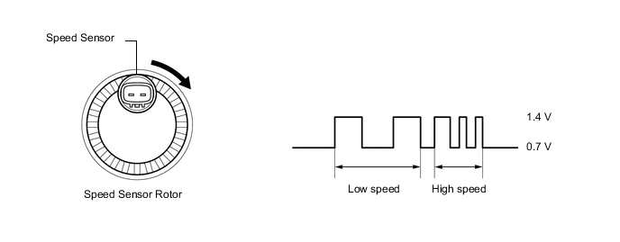
Each speed sensor detects the wheel speed and sends the signals to the skid control ECU (brake booster with master cylinder assembly). These signals are used for ABS control.
Tech Tips
The output voltage values shown below are for when the vehicle wire harnesses are connected to the skid control ECU (brake booster with master cylinder assembly) and the speed sensors.
| DTC No. | Detection Item | INF Code | DTC Detection Condition | Trouble Area | Note |
|---|---|---|---|---|---|
| C1415 | Rear Speed Sensor RH Circuit Output | 524 543 |
|
|
ABS DTC |
| C1416 | Rear Speed Sensor LH Circuit Output | 534 544 |
|
|
ABS DTC |
| Vehicle Condition | |||
|---|---|---|---|
| Pattern 1 | Pattern 2 | ||
| Diagnosis Condition | At a vehicle speed of 20 km/h (12 mph) or more. | ○ | - |
| At a vehicle speed of 10 km/h (6 mph) or more. | - | ○ | |
| Malfunction Status | Noise occurs in the sensor signals of a malfunctioning wheel. | ○ | - |
| Noise occurs once per rotor rotation. | - | ○ | |
| Detection Time | Detected 75 times or more within 5 seconds | 15 seconds or more | |
| Number of Trips | 1 trip | 1 trip | |
Tech Tips
DTC will be output when conditions for either of the patterns in the table above are met.
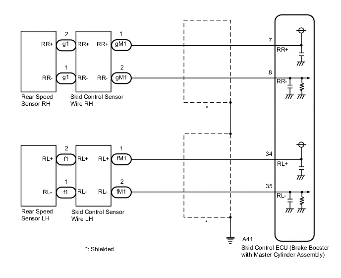
WIRING DIAGRAM
CAUTION / NOTICE / HINT
Note
After replacing the skid control ECU (brake booster with master cylinder assembly), perform linear solenoid valve offset learning, ABS holding solenoid valve learning, yaw rate and acceleration sensor zero point calibration and system information memorization after performing "Reset Memory".
PROCEDURE
-
CLEAR DTC
-
Clear the DTCs.
Chassis > ABS/VSC/TRC > Clear DTCsResult Proceed to NEXT
NEXT 
-
-
CHECK DTC
-
Turn the power switch off.
-
Turn the power switch on (IG).
-
Check if the same DTC is output.
Chassis > ABS/VSC/TRC > Trouble CodesResult Result Proceed to C1415 is output A C1416 is output B
B 
READ VALUE USING GTS (MOMENTARY INTERRUPTION) Click here
A
-
-
READ VALUE USING GTS (MOMENTARY INTERRUPTION)
-
Using the GTS, check for any momentary interruptions in the wire harness and connector corresponding to a DTC.
Chassis > ABS/VSC/TRC > Data ListTester Display Measurement Item Range Normal Condition Diagnostic Note RR Speed Sensor Voltage Open Rear speed sensor RH voltage open detection Error or Normal Error: Momentary interruption
Normal: Normal
-
Chassis > ABS/VSC/TRC > Data ListTester Display RR Speed Sensor Voltage Open -
Check for any momentary interruptions in the wire harness and connectors.
Note
Perform the above inspection before removing the sensor and connector.
Result Result Proceed to The value of RR Speed Sensor Voltage Open is always Normal A The value of RR Speed Sensor Voltage Open outputs Error one or more times B
B
CHECK REAR SPEED SENSOR RH INSTALLATION Click here
A
-
-
READ VALUE USING GTS (REAR SPEED SENSOR RH)
-
Select the Data List on the GTS.
Chassis > ABS/VSC/TRC > Data ListTester Display Measurement Item Range Normal Condition Diagnostic Note RR Wheel Speed Rear speed sensor RH Min.: 0 km/h (0 mph), Max.: 326.4 km/h (203 mph) Vehicle stopped: 0 km/h (0 mph) When driving at constant speed: No large fluctuations
Chassis > ABS/VSC/TRC > Data ListTester Display RR Wheel Speed -
Check the rear speed sensor RH output value.
Result Result Proceed to The value of RR Wheel Speed changes in accordance with the vehicle speed A Other than above B
B
GO TO STEP 7 Click here
A
-
-
CLEAR DTC
-
Clear the DTCs.
Chassis > ABS/VSC/TRC > Clear DTCsResult Proceed to NEXT
NEXT
-
-
RECONFIRM DTC
-
Turn the power switch off.
-
Turn the power switch on (READY).
-
Perform a road test.
-
Check if the same DTC is output.
Chassis > ABS/VSC/TRC > Trouble CodesResult Result Proceed to C1415 is not output A C1415 is output B
A 
USE SIMULATION METHOD TO CHECK Click here
B
REPLACE BRAKE BOOSTER WITH MASTER CYLINDER ASSEMBLY for LHD: Click here
REPLACE BRAKE BOOSTER WITH MASTER CYLINDER ASSEMBLY for RHD: Click here -
-
CHECK REAR SPEED SENSOR RH INSTALLATION
-
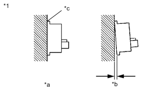
*1 Rear Speed Sensor RH *a OK *b NG *c No Clearance Turn the power switch off.
-
Check the rear speed sensor RH installation.
OK There is no clearance between the sensor and the rear axle hub. Tech Tips
Because the rear axle hub and bearing assembly RH cannot be disassembled, if the rear speed sensor RH needs replacement, replace the rear axle hub and bearing assembly RH.
Result Proceed to OK NG
NG
REPLACE REAR AXLE HUB AND BEARING ASSEMBLY RH Click here
OK
-
-
INSPECT SKID CONTROL SENSOR WIRE RH
-
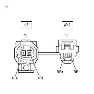
*a Front view of skid control sensor wire RH *b Front view of wire harness connector
(to Sensor Side Connector)
*c Front view of wire harness connector
(to Vehicle Side Connector)
Make sure that there is no looseness at the locking part and the connecting part of the connectors.
OK The connector is securely connected. -
Remove the skid control sensor wire RH.
-
Check both the connector case and the terminals for deformation and corrosion.
OK No deformation or corrosion. -
Measure the resistance according to the value(s) in the table below.
Standard Resistance Tester Connection Condition Specified Condition g1-2 (RR+) - gM1 -1 (RR+) Always Below 1 Ω g1-2 (RR+) - gM1 -2 (RR-) Always 10 kΩ or higher g1-2 (RR+) or gM1 -1 (RR+) - Body ground Always 10 kΩ or higher g1-1 (RR-) - gM1 -2 (RR-) Always Below 1 Ω g1-1 (RR-) - gM1 -1 (RR+) Always 10 kΩ or higher g1-1 (RR-) or gM1 -2 (RR-) - Body ground Always 10 kΩ or higher Result Proceed to OK NG
NG
REPLACE SKID CONTROL SENSOR WIRE RH
OK
-
-
CHECK HARNESS AND CONNECTOR (BRAKE BOOSTER WITH MASTER CYLINDER ASSEMBLY - SKID CONTROL SENSOR WIRE RH)
-
Make sure that there is no looseness at the locking part and the connecting part of the connector.
OK The connector is securely connected. -
Disconnect the A41 skid control ECU (brake booster with master cylinder assembly) connector.
-
Check both the connector case and the terminals for deformation and corrosion.
OK No deformation or corrosion. -
Measure the resistance according to the value(s) in the table below.
Standard Resistance Tester Connection Condition Specified Condition A41-7 (RR+) - gM1 -1 (RR+) Always Below 1 Ω A41-7 (RR+) or gM1 -1 (RR+) - Body ground Always 10 kΩ or higher A41-8 (RR-) - gM1 -2 (RR-) Always Below 1 Ω A41-8 (RR-) or gM1 -2 (RR-) - Body ground Always 10 kΩ or higher Result Proceed to OK NG
NG
REPAIR OR REPLACE HARNESS OR CONNECTOR
OK
-
-
INSPECT BRAKE BOOSTER WITH MASTER CYLINDER ASSEMBLY (SENSOR OUTPUT)
-
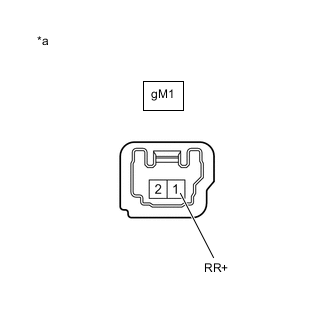
*a Front view of wire harness connector
(to Skid Control Sensor Wire RH)
Reconnect the A41 skid control ECU (brake booster with master cylinder assembly) connector.
-
Turn the power switch on (IG).
-
Measure the voltage according to the value(s) in the table below.
Standard Voltage Tester Connection Condition Specified Condition gM1 -1 (RR+) - Body ground Power switch on (IG) 8 to 14 V Tech Tips
The rear speed sensor RH and rear speed sensor rotor RH are incorporated into the rear axle hub and bearing assembly RH.
If the rear speed sensor RH and rear speed sensor rotor RH need to be replaced, replace the rear axle hub and bearing assembly RH.
Result Proceed to OK NG
OK
REPLACE REAR AXLE HUB AND BEARING ASSEMBLY RH Click here
NG
REPLACE BRAKE BOOSTER WITH MASTER CYLINDER ASSEMBLY for LHD: Click here
REPLACE BRAKE BOOSTER WITH MASTER CYLINDER ASSEMBLY for RHD: Click here -
-
READ VALUE USING GTS (MOMENTARY INTERRUPTION)
-
Using the GTS, check for any momentary interruptions in the wire harness and connector corresponding to a DTC.
Chassis > ABS/VSC/TRC > Data ListTester Display Measurement Item Range Normal Condition Diagnostic Note RL Speed Sensor Voltage Open Rear speed sensor LH voltage open detection Error or Normal Error: Momentary interruption
Normal: Normal
-
Chassis > ABS/VSC/TRC > Data ListTester Display RL Speed Sensor Voltage Open -
Check for any momentary interruptions in the wire harness and connectors.
Note
Perform the above inspection before removing the sensor and connector.
Result Result Proceed to The value of RL Speed Sensor Voltage Open is always Normal A The value of RL Speed Sensor Voltage Open outputs Error one or more times B
B
CHECK REAR SPEED SENSOR LH INSTALLATION Click here
A
-
-
READ VALUE USING GTS (REAR SPEED SENSOR LH)
-
Select the Data List on the GTS.
Chassis > ABS/VSC/TRC > Data ListTester Display Measurement Item Range Normal Condition Diagnostic Note RL Wheel Speed Rear speed sensor LH Min.: 0 km/h (0 mph), Max.: 326.4 km/h (203 mph) Vehicle stopped: 0 km/h (0 mph) When driving at constant speed: No large fluctuations
Chassis > ABS/VSC/TRC > Data ListTester Display RL Wheel Speed -
Check the rear speed sensor LH output value.
Result Result Proceed to The value of RL Wheel Speed changes in accordance with the vehicle speed A Other than above B
B
GO TO STEP 15 Click here
A
-
-
CLEAR DTC
-
Clear the DTCs.
Chassis > ABS/VSC/TRC > Clear DTCsResult Proceed to NEXT
NEXT
-
-
RECONFIRM DTC
-
Turn the power switch off.
-
Turn the power switch on (READY).
-
Perform a road test.
-
Check if the same DTC is output.
Chassis > ABS/VSC/TRC > Trouble CodesResult Result Proceed to C1416 is not output A C1416 is output B
A
USE SIMULATION METHOD TO CHECK Click here
B
REPLACE BRAKE BOOSTER WITH MASTER CYLINDER ASSEMBLY for LHD: Click here
REPLACE BRAKE BOOSTER WITH MASTER CYLINDER ASSEMBLY for RHD: Click here -
-
CHECK REAR SPEED SENSOR LH INSTALLATION
-
*1 Rear Speed Sensor LH *a OK *b NG *c No Clearance Turn the power switch off.
-
Check the rear speed sensor LH installation.
OK There is no clearance between the sensor and the rear axle hub. Tech Tips
Because the rear axle hub and bearing assembly LH cannot be disassembled, if the rear speed sensor LH needs replacement, replace the rear axle hub and bearing assembly LH.
Result Proceed to OK NG
NG
REPLACE REAR AXLE HUB AND BEARING ASSEMBLY LH Click here
OK
-
-
INSPECT SKID CONTROL SENSOR WIRE LH
-
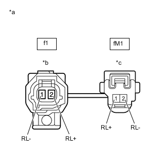
*a Front view of skid control sensor wire LH *b Front view of wire harness connector
(to Sensor Side Connector)
*c Front view of wire harness connector
(to Vehicle Side Connector)
Make sure that there is no looseness at the locking part and the connecting part of the connectors.
OK The connector is securely connected. -
Remove the skid control sensor wire LH.
-
Check both the connector case and the terminals for deformation and corrosion.
OK No deformation or corrosion. -
Measure the resistance according to the value(s) in the table below.
Standard Resistance Tester Connection Condition Specified Condition f1-2 (RL+) - fM1 -1 (RL+) Always Below 1 Ω f1-2 (RL+) - fM1 -2 (RL-) Always 10 kΩ or higher f1-2 (RL+) or fM1 -1 (RL+) - Body ground Always 10 kΩ or higher f1-1 (RL-) - fM1 -2 (RL-) Always Below 1 Ω f1-1 (RL-) - fM1 -1 (RL+) Always 10 kΩ or higher f1-1 (RL-) or fM1 -2 (RL-) - Body ground Always 10 kΩ or higher Result Proceed to OK NG
NG
REPLACE SKID CONTROL SENSOR WIRE LH
OK
-
-
CHECK HARNESS AND CONNECTOR (BRAKE BOOSTER WITH MASTER CYLINDER ASSEMBLY - SKID CONTROL SENSOR WIRE LH)
-
Make sure that there is no looseness at the locking part and the connecting part of the connector.
OK The connector is securely connected. -
Disconnect the A41 skid control ECU (brake booster with master cylinder assembly) connector.
-
Check both the connector case and the terminals for deformation and corrosion.
OK No deformation or corrosion. -
Measure the resistance according to the value(s) in the table below.
Standard Resistance Tester Connection Condition Specified Condition A41-34 (RL+) - fM1 -1 (RL+) Always Below 1 Ω A41-34 (RL+) or fM1 -1 (RL+) - Body ground Always 10 kΩ or higher A41-35 (RL-) - fM1 -2 (RL-) Always Below 1 Ω A41-35 (RL-) or fM1 -2 (RL-) - Body ground Always 10 kΩ or higher Result Proceed to OK NG
NG
REPAIR OR REPLACE HARNESS OR CONNECTOR
OK
-
-
INSPECT BRAKE BOOSTER WITH MASTER CYLINDER ASSEMBLY (SENSOR OUTPUT)
-
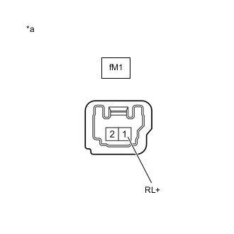
*a Front view of wire harness connector
(to Skid Control Sensor Wire LH)
Reconnect the A41 skid control ECU (brake booster with master cylinder assembly) connector.
-
Turn the power switch on (IG).
-
Measure the voltage according to the value(s) in the table below.
Standard Voltage Tester Connection Condition Specified Condition fM1 -1 (RL+) - Body ground Power switch on (IG) 8 to 14 V Tech Tips
The rear speed sensor LH and rear speed sensor rotor LH are incorporated into the rear axle hub and bearing assembly LH.
If the rear speed sensor LH and rear speed sensor rotor LH need to be replaced, replace the rear axle hub and bearing assembly LH.
Result Proceed to OK NG
OK
REPLACE REAR AXLE HUB AND BEARING ASSEMBLY LH Click here
NG
REPLACE BRAKE BOOSTER WITH MASTER CYLINDER ASSEMBLY for LHD: Click here
REPLACE BRAKE BOOSTER WITH MASTER CYLINDER ASSEMBLY for RHD: Click here -