ELECTRONICALLY CONTROLLED BRAKE SYSTEM, Diagnostic DTC:C1401, C1402
| DTC Code | DTC Name |
|---|---|
| C1401 | Malfunction in Front Speed Sensor RH Circuit |
| C1402 | Malfunction in Front Speed Sensor LH Circuit |
DESCRIPTION
Refer to DTCs C1413 and C1414.
| DTC No. | Detection Item | INF Code | DTC Detection Condition | Trouble Area | Note |
|---|---|---|---|---|---|
| C1401 | Malfunction in Front Speed Sensor RH Circuit | 501 502 507 |
|
|
ABS DTC |
| C1402 | Malfunction in Front Speed Sensor LH Circuit | 511 512 517 |
|
|
ABS DTC |
PROCEDURE
-
CLEAR DTC
-
Clear the DTCs.
Chassis > ABS/VSC/TRC > Clear DTCsResult Proceed to NEXT
NEXT 
-
-
CHECK DTC
-
Turn the power switch off.
-
Turn the power switch on (IG).
-
Check if the same DTC is output.
Chassis > ABS/VSC/TRC > Trouble CodesResult Result Proceed to C1401 is output A C1402 is output B
B 
CHECK FRONT SPEED SENSOR LH INSTALLATION Click here
A
-
-
CHECK FRONT SPEED SENSOR RH INSTALLATION
-
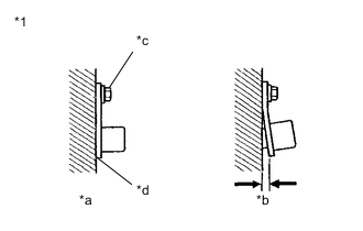
*1 Front Speed Sensor RH *a OK *b NG *c 8.5 N*m *d No Clearance Check the front speed sensor RH installation.
OK There is no clearance between the sensor and the front steering knuckle. The installation bolt is tightened properly. Torque 8.5 N*m (87 kgf*cm, 75 in.*lbf) Result Proceed to OK NG
NG 
REINSTALL OR REPLACE FRONT SPEED SENSOR RH Click here
OK
-
-
CHECK FRONT SPEED SENSOR RH (CHECK FOR FOREIGN MATTER)
-
Remove the front speed sensor RH.
Tech Tips
-
Check the front speed sensor tip RH.
OK The front speed sensor tip RH is free of scratches, oil, and foreign matter. Note
-
If there is oil or foreign matter on the front speed sensor RH, clean the front speed sensor RH.
-
If the front speed sensor RH is damaged, replace the front speed sensor RH with a new one.
-
Check the front speed sensor RH signal after cleaning or replacement.
Result Proceed to OK NG -
NG
CLEAN OR REPLACE FRONT SPEED SENSOR RH
OK
-
-
READ VALUE USING GTS (FRONT SPEED SENSOR RH)
-
Install the front speed sensor RH.
-
Select the Data List on the GTS.
Chassis > ABS/VSC/TRC > Data ListTester Display Measurement Item Range Normal Condition Diagnostic Note FR Wheel Speed Front speed sensor RH Min.: 0 km/h (0 mph), Max.: 326.4 km/h (203 mph) Vehicle stopped: 0 km/h (0 mph) When driving at constant speed: No large fluctuations
Chassis > ABS/VSC/TRC > Data ListTester Display FR Wheel Speed -
Check the front speed sensor RH output value.
Result Result Proceed to The value of FR Wheel Speed changes in accordance with the vehicle speed A Other than above B
A
USE SIMULATION METHOD TO CHECK Click here
B
-
-
CHECK HARNESS AND CONNECTOR (BRAKE BOOSTER WITH MASTER CYLINDER ASSEMBLY - FRONT SPEED SENSOR RH)
-
Turn the power switch off.
-
Make sure that there is no looseness at the locking part and the connecting part of the connectors.
OK The connector is securely connected. -
Disconnect the A41 skid control ECU (brake booster with master cylinder assembly) connector.
-
Disconnect the A31 front speed sensor RH connector.
-
Check both the connector case and the terminals for deformation and corrosion.
OK No deformation or corrosion. -
Measure the resistance according to the value(s) in the table below.
Standard Resistance Tester Connection Condition Specified Condition A41-3 (FR+) - A31-1 (FR+) Always Below 1 Ω A41-3 (FR+) or A31-1 (FR+) - Body ground Always 10 kΩ or higher A41-4 (FR-) - A31-2 (FR-) Always Below 1 Ω A41-4 (FR-) or A31-2 (FR-) - Body ground Always 10 kΩ or higher Result Proceed to OK NG
NG
REPAIR OR REPLACE HARNESS OR CONNECTOR
OK
-
-
CHECK FRONT SPEED SENSOR ROTOR RH (CHECK FOR FOREIGN MATTER)
-
Remove the front speed sensor RH and the component with the front speed sensor rotor RH.
-
Check the front speed sensor rotor RH.
OK The front speed sensor rotor RH is free of scratches, oil, and foreign matter. Note
-
If there is oil or foreign matter on the front speed sensor rotor RH, clean the front speed sensor rotor RH.
-
If the front speed sensor rotor RH is damaged, replace the front speed sensor rotor RH with a new one.
-
Check the front speed sensor RH signal after cleaning or replacement.
Tech Tips
-
The front speed sensor rotor RH is incorporated into the front axle hub sub-assembly RH.
-
If the front speed sensor rotor RH needs to be replaced, replace it together with the front axle hub sub-assembly RH.
Result Result Proceed to OK A NG (The front speed sensor rotor RH is damaged.) B NG (There is foreign matter on the front speed sensor rotor RH.) C -
A
REPLACE FRONT SPEED SENSOR RH Click here
B
REPLACE FRONT AXLE HUB SUB-ASSEMBLY RH Click here
C
CLEAN FRONT SPEED SENSOR ROTOR RH
-
-
CHECK FRONT SPEED SENSOR LH INSTALLATION
-
*1 Front Speed Sensor LH *a OK *b NG *c 8.5 N*m *d No Clearance Check the front speed sensor LH installation.
OK There is no clearance between the sensor and the front steering knuckle. The installation bolt is tightened properly. Torque 8.5 N*m (87 kgf*cm, 75 in.*lbf) Result Proceed to OK NG
NG
REINSTALL OR REPLACE FRONT SPEED SENSOR LH Click here
OK
-
-
CHECK FRONT SPEED SENSOR LH (CHECK FOR FOREIGN MATTER)
-
Remove the front speed sensor LH.
Tech Tips
-
Check the front speed sensor tip LH.
OK The front speed sensor tip LH is free of scratches, oil, and foreign matter. Note
-
If there is oil or foreign matter on the front speed sensor LH, clean the front speed sensor LH.
-
If the front speed sensor LH is damaged, replace the front speed sensor LH with a new one.
-
Check the front speed sensor LH signal after cleaning or replacement.
Result Proceed to OK NG -
NG
CLEAN OR REPLACE FRONT SPEED SENSOR LH
OK
-
-
READ VALUE USING GTS (FRONT SPEED SENSOR LH)
-
Install the front speed sensor LH.
-
Select the Data List on the GTS.
Chassis > ABS/VSC/TRC > Data ListTester Display Measurement Item Range Normal Condition Diagnostic Note FL Wheel Speed Front speed sensor LH Min.: 0 km/h (0 mph), Max.: 326.4 km/h (203 mph) Vehicle stopped: 0 km/h (0 mph) When driving at constant speed: No large fluctuations
Chassis > ABS/VSC/TRC > Data ListTester Display FL Wheel Speed -
Check the front speed sensor LH output value.
Result Result Proceed to The value of FL Wheel Speed changes in accordance with the vehicle speed A Other than above B
A
USE SIMULATION METHOD TO CHECK Click here
B
-
-
CHECK HARNESS AND CONNECTOR (BRAKE BOOSTER WITH MASTER CYLINDER ASSEMBLY - FRONT SPEED SENSOR LH)
-
Turn the power switch off.
-
Make sure that there is no looseness at the locking part and the connecting part of the connectors.
OK The connector is securely connected. -
Disconnect the A41 skid control ECU (brake booster with master cylinder assembly) connector.
-
Disconnect the A15 front speed sensor LH connector.
-
Check both the connector case and the terminals for deformation and corrosion.
OK No deformation or corrosion. -
Measure the resistance according to the value(s) in the table below.
Standard Resistance Tester Connection Condition Specified Condition A41-31 (FL+) - A15-1 (FL+) Always Below 1 Ω A41-31 (FL+) or A15-1 (FL+) - Body ground Always 10 kΩ or higher A41-32 (FL-) - A15-2 (FL-) Always Below 1 Ω A41-32 (FL-) or A15-2 (FL-) - Body ground Always 10 kΩ or higher Result Proceed to OK NG
NG
REPAIR OR REPLACE HARNESS OR CONNECTOR
OK
-
-
CHECK FRONT SPEED SENSOR ROTOR LH (CHECK FOR FOREIGN MATTER)
-
Remove the front speed sensor LH and the component with the front speed sensor rotor LH.
-
Check the front speed sensor rotor LH.
OK The front speed sensor rotor LH is free of scratches, oil, and foreign matter. Note
-
If there is oil or foreign matter on the front speed sensor rotor LH, clean the front speed sensor rotor LH.
-
If the front speed sensor rotor LH is damaged, replace the front speed sensor rotor LH with a new one.
-
Check the front speed sensor LH signal after cleaning or replacement.
Tech Tips
-
The front speed sensor rotor LH is incorporated into the front axle hub sub-assembly LH.
-
If the front speed sensor rotor LH needs to be replaced, replace it together with the front axle hub sub-assembly LH.
Result Result Proceed to OK A NG (The front speed sensor rotor LH is damaged.) B NG (There is foreign matter on the front speed sensor rotor LH.) C -
A
REPLACE FRONT SPEED SENSOR LH Click here
B
REPLACE FRONT AXLE HUB SUB-ASSEMBLY LH Click here
C
CLEAN FRONT SPEED SENSOR ROTOR LH
-