REAR SUSPENSION MEMBER INSTALLATION
PROCEDURE
-
INSTALL HOLE PLUG
-
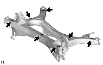
Install the 7 hole plugs to the rear suspension member sub-assembly as shown in the illustration.
-
-
INSTALL REAR SUSPENSION MEMBER HOLE COVER
-
Install the 4 rear suspension member hole covers to the rear suspension member sub-assembly.
-
-
INSTALL REAR UPPER CONTROL ARM ASSEMBLY LH
-
INSTALL REAR UPPER CONTROL ARM ASSEMBLY RH
Tech Tips
Perform the same procedure as for the LH side.
-
INSTALL REAR SUSPENSION MEMBER SUB-ASSEMBLY
-
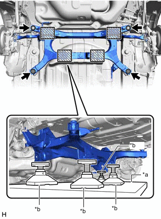
*a Engine Lifter *b Attachment 
Attachment and Wooden Block Placement Location Using an engine lifter and 4 attachments or equivalent tools, support the rear suspension member sub-assembly as shown in the illustration.
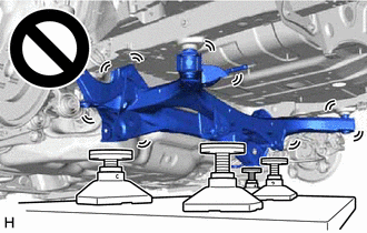
CAUTION:
-
The rear suspension member sub-assembly is a very heavy component. Make sure that it is supported securely.
-
If the rear suspension member sub-assembly is not securely supported, it may drop, resulting in serious injury.
Note
-
Use attachments and wooden blocks to keep the rear suspension member sub-assembly level.
-
Keep supporting the rear suspension member sub-assembly until the installation has been completed.
-
-
Raise the rear suspension member sub-assembly until there is no clearance between the rear suspension member sub-assembly and vehicle.
-
Install the rear suspension member sub-assembly with the 2 bolts and 2 nuts.
- Torque:
- 143 N*m { 1458 kgf*cm, 105 ft.*lbf }
-
-
TEMPORARILY INSTALL REAR UPPER CONTROL ARM ASSEMBLY LH
-
Temporarily install the rear upper control arm assembly LH to the rear axle carrier sub-assembly LH with the bolt and nut.
Note
-
Insert the bolt with the threaded end facing the rear of the vehicle.
-
Because the nut has its own stopper, do not turn the nut. Tighten the bolt with the nut secured.
-
-
-
TEMPORARILY INSTALL REAR UPPER CONTROL ARM ASSEMBLY RH
Tech Tips
Perform the same procedure as for the LH side.
-
TEMPORARILY INSTALL REAR NO. 1 SUSPENSION ARM ASSEMBLY LH
-
TEMPORARILY INSTALL REAR NO. 1 SUSPENSION ARM ASSEMBLY RH
Tech Tips
Perform the same procedure as for the LH side.
-
TEMPORARILY INSTALL REAR NO. 2 SUSPENSION ARM ASSEMBLY LH
-
TEMPORARILY INSTALL REAR NO. 2 SUSPENSION ARM ASSEMBLY RH
Tech Tips
Perform the same procedure as for the LH side.
-
INSTALL REAR LOWER COIL SPRING INSULATOR LH
-
INSTALL REAR LOWER COIL SPRING INSULATOR RH
Tech Tips
Perform the same procedure as for the LH side.
-
INSTALL REAR COIL SPRING LH
-
INSTALL REAR COIL SPRING RH
Tech Tips
Perform the same procedure as for the LH side.
-
INSTALL REAR STABILIZER BAR
-
INSTALL REAR HEIGHT CONTROL SENSOR SUB-ASSEMBLY LH
-
Install the rear height control sensor sub-assembly LH with the 2 bolts.
- Torque:
- 8.0 N*m { 82 kgf*cm, 71 in.*lbf }
-
Connect the connector and engage the 2 clamps.
-
-
CONNECT REAR FLEXIBLE HOSE LH
-
Connect the rear flexible hose LH to the flexible hose bracket with the bolt.
- Torque:
- 29 N*m { 296 kgf*cm, 21 ft.*lbf }
-
-
CONNECT REAR FLEXIBLE HOSE RH
Tech Tips
Perform the same procedure as for the LH side.
-
STABILIZE SUSPENSION
-
INSTALL REAR STABILIZER LINK ASSEMBLY LH
-
INSTALL REAR STABILIZER LINK ASSEMBLY RH
Tech Tips
Perform the same procedure as for the LH side.
-
INSTALL REAR NO. 1 SUSPENSION ARM ASSEMBLY LH
-
INSTALL REAR NO. 1 SUSPENSION ARM ASSEMBLY RH
Tech Tips
Perform the same procedure as for the LH side.
-
INSTALL REAR NO. 2 SUSPENSION ARM ASSEMBLY LH
-
Install the rear No. 2 suspension arm assembly LH (rear axle carrier sub-assembly side) with the bolt.
-
-
INSTALL REAR NO. 2 SUSPENSION ARM ASSEMBLY RH
Tech Tips
Perform the same procedure as for the LH side.
-
INSTALL REAR UPPER CONTROL ARM ASSEMBLY LH
-
Install the rear upper control arm assembly LH to the rear axle carrier sub-assembly LH with the bolt.
- Torque:
- 73 N*m { 744 kgf*cm, 54 ft.*lbf }
Note
Because the nut has its own stopper, do not turn the nut. Tighten the bolt with the nut secured.
-
-
INSTALL REAR UPPER CONTROL ARM ASSEMBLY RH
Tech Tips
Perform the same procedure as for the LH side.
-
INSTALL REAR FLOOR SIDE MEMBER COVER LH
w/ Canister Pump Module: Click here
w/o Canister Pump Module: Click here
-
INSTALL NO. 1 FLOOR UNDER COVER ASSEMBLY
w/ Canister Pump Module: Click here
w/o Canister Pump Module: Click here
-
INSTALL TAIL EXHAUST PIPE ASSEMBLY
-
INSTALL REAR WHEEL
-
INSTALL REAR NO. 2 SUSPENSION ARM ASSEMBLY LH
-
Install the rear No. 2 suspension arm assembly LH (rear suspension member sub-assembly side) with the nut.
-
-
INSTALL REAR NO. 2 SUSPENSION ARM ASSEMBLY RH
Tech Tips
Perform the same procedure as for the LH side.
-
INSPECT FOR EXHAUST GAS LEAK
-
INSPECT AND ADJUST REAR WHEEL ALIGNMENT
-
PERFORM INITIALIZATION
Intelligent clearance sonar system
Simple intelligent parking assist system
Parking assist monitor system Automatic headlight beam level control system