REAR COIL SPRING REMOVAL
CAUTION / NOTICE / HINT
The necessary procedures (adjustment, calibration, initialization, or registration) that must be performed after parts are removed and installed, or replaced during rear coil spring removal/installation are shown below.
| Replaced Part or Performed Procedure | Necessary Procedure | Effect/Inoperative Function when Necessary Procedure not Performed | Link |
|---|---|---|---|
| Rear wheel alignment adjustment |
|
|
|
| Suspension, tires, etc. (The vehicle height changes because of suspension or tire replacement) |
|
|
|
| Rear television camera assembly optical axis (Back camera position setting) | Parking assist monitor system | ||
|
Initialize No. 1 headlight ECU sub-assembly LH | Automatic headlight beam level control system |
Tech Tips
-
Use the same procedure for the RH side and LH side.
-
The following procedure is for the LH side.
PROCEDURE
-
REMOVE REAR WHEEL
-
REMOVE REAR FLOOR SIDE MEMBER COVER LH (for LH Side)
w/ Canister Pump Module: Click here
w/o Canister Pump Module: Click here
-
REMOVE NO. 1 FLOOR UNDER COVER ASSEMBLY (for RH Side)
w/ Canister Pump Module: Click here
w/o Canister Pump Module: Click here
-
REMOVE REAR HEIGHT CONTROL SENSOR SUB-ASSEMBLY LH (for LH Side)
-
REMOVE REAR COIL SPRING
-
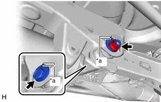
*a Matchmark Place matchmarks on the No. 2 camber adjust cam, rear suspension toe adjust cam sub-assembly and rear suspension member sub-assembly.
-
Loosen the nut (rear suspension member sub-assembly side) of the rear No. 2 suspension arm assembly.
Note
Hold the rear suspension toe adjust cam sub-assembly while rotating the nut.
-
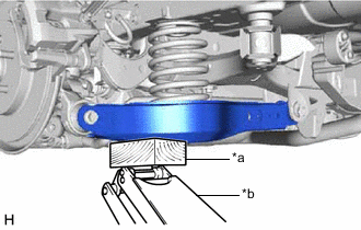
*a Wooden Block *b Jack Using a jack and a wooden block, support the rear No. 2 suspension arm assembly.
Note
-
When jacking up the rear No. 2 suspension arm assembly, be sure to jack it up slowly.
-
Make sure to perform this operation with the vehicle kept as low as possible.
-
-
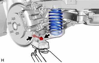
Remove the bolt and nut, and separate the rear No. 2 suspension arm assembly from the rear axle carrier sub-assembly.
Note
Because the nut has its own stopper, do not turn the nut. Loosen the bolt with the nut secured.
-
Slowly lower the rear No. 2 suspension arm assembly, and then remove the rear coil spring.
-
-
REMOVE REAR UPPER COIL SPRING INSULATOR
-
Remove the rear upper coil spring insulator from the vehicle.
-
-
REMOVE REAR LOWER COIL SPRING INSULATOR
-
Remove the rear lower coil spring insulator from the rear No. 2 suspension arm assembly.
-