FRONT AXLE HUB REMOVAL
CAUTION / NOTICE / HINT
The necessary procedures (adjustment, calibration, initialization, or registration) that must be performed after parts are removed and installed, or replaced during front axle hub sub-assembly removal/installation are shown below.
| Replaced Part or Performed Procedure | Necessary Procedure | Effect/Inoperative Function when Necessary Procedure not Performed | Link |
|---|---|---|---|
| Front wheel alignment adjustment |
|
|
|
| Auxiliary battery terminal is disconnected/reconnected | Memorize steering angle neutral point | Lane departure alert system (w/ Steering Control) | |
| Intelligent clearance sonar system | |||
| Simple intelligent parking assist system | |||
| Pre-crash safety system | |||
| Parking assist monitor system | |||
| Initialize back door lock | Power door lock control system |
Note
-
When removing or installing the front disc brake caliper assembly, pushing back the disc brake piston may cause a large clearance between the brake pads and brake disc. When the brake pedal is depressed with a large clearance between the brake pads and the brake disc, DTC C1214 related to abnormal brake fluid pressure may be stored. Make sure to clear any DTCs after performing this step.
-
While the auxiliary battery is connected, even if the power switch is off, the brake control system activates when the brake pedal is depressed or any door courtesy switch turns on. Therefore, when servicing the brake system components, do not operate the brake pedal or open/close the doors while the auxiliary battery is connected.
Tech Tips
-
Use the same procedure for the RH side and LH side.
-
The following procedure is for the LH side.
PROCEDURE
-
PRECAUTION
Note
After turning the power switch off, waiting time may be required before disconnecting the cable from the negative (-) auxiliary battery terminal. Therefore, make sure to read the disconnecting the cable from the negative (-) auxiliary battery terminal notices before proceeding with work.
-
DISABLE BRAKE CONTROL
-
REMOVE FRONT WHEEL
-
REMOVE FRONT AXLE SHAFT NUT
-
SEPARATE FRONT SPEED SENSOR
-
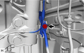
Remove the bolt and separate the front speed sensor and front flexible hose from the front shock absorber assembly.
Note
Be sure to separate the front speed sensor and front flexible hose from the front shock absorber assembly completely.
-
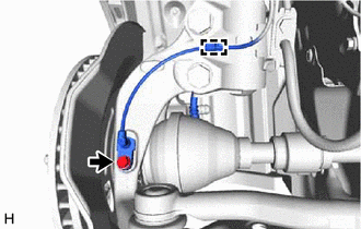
Remove the bolt, disengage the clamp and separate the front speed sensor from the front shock absorber assembly and steering knuckle.
Note
-
Prevent foreign matter from contacting the sensor tip.
-
Be careful not to damage the front speed sensor.
-
Clean the speed sensor installation hole and the contact surfaces every time the speed sensor is removed.
-
-
-
SEPARATE TIE ROD END SUB-ASSEMBLY
-
SEPARATE FRONT DISC BRAKE CALIPER ASSEMBLY
-
REMOVE FRONT DISC
-
SEPARATE FRONT LOWER NO. 1 SUSPENSION ARM SUB-ASSEMBLY
-
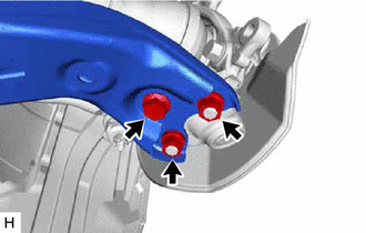
Remove the bolt and 2 nuts and separate the front lower No. 1 suspension arm sub-assembly from the front lower ball joint assembly.
-
-
SEPARATE FRONT DRIVE SHAFT ASSEMBLY
-
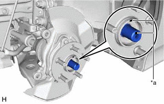
*a Matchmark Put matchmarks on the front drive shaft assembly and the front axle hub sub-assembly.
-
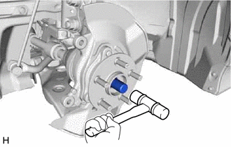
Using a plastic hammer, separate the front drive shaft assembly from the front axle assembly.
Note
-
Do not damage the front drive shaft outboard joint boot.
-
Do not push the front axle assembly towards the outside of the vehicle any further than necessary.
Tech Tips
If it is difficult to separate the front drive shaft assembly from the front axle assembly, tap the end of the front drive shaft assembly using a brass bar and a hammer.
-
-
-
REMOVE FRONT AXLE ASSEMBLY
-
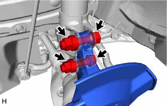
Remove the 2 bolts, 2 nuts and front axle assembly from the front shock absorber assembly.
Note
When removing the nuts, keep the bolts from rotating.
-
-
REMOVE FRONT AXLE HUB SUB-ASSEMBLY
-
Secure the front axle assembly between aluminum plates in a vise.
Note
Do not overtighten the vise.
-
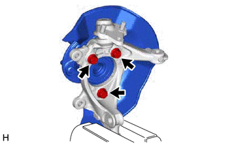
Remove the 3 bolts, front axle hub sub-assembly and front disc brake dust cover from the steering knuckle.
Note
-
Do not drop the front axle hub sub-assembly.
-
Be careful not to damage the speed sensor rotor or contact surfaces.
-
Do not allow foreign matter to contact the speed sensor rotor or contact surfaces.
-
-