SHIFT LEVER REMOVAL
CAUTION / NOTICE / HINT
The necessary procedures (adjustment, calibration, initialization or registration) that must be performed after parts are removed and installed, or replaced during shift lock control unit assembly removal/installation are shown below.
| Replaced Part or Performed Procedure | Necessary Procedure | Effect/Inoperative Function when Necessary Procedure not Performed | Link |
|---|---|---|---|
| Disconnect cable from negative auxiliary battery terminal | Memorize steering angle neutral point | Lane departure alert system (w/ Steering Control) | |
| Intelligent clearance sonar system*1 | |||
| Simple intelligent parking assist system*1 | |||
| Pre-crash safety system | |||
| Parking assist monitor system | |||
| Initialize back door lock | Power door lock control system |
Click here Click here
PROCEDURE
-
PRECAUTION
Note
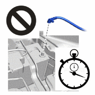
After turning the power switch off, waiting time may be required before disconnecting the cable from the negative (-) auxiliary battery terminal. Therefore, make sure to read the disconnecting the cable from the negative (-) auxiliary battery terminal notices before proceeding with work.
-
DISCONNECT CABLE FROM NEGATIVE AUXILIARY BATTERY TERMINAL
CAUTION:
Wait at least 90 seconds after disconnecting the cable from the negative (-) auxiliary battery terminal to disable the SRS system.
Note
When disconnecting the cable, some systems need to be initialized after the cable is reconnected.
-
REMOVE REAR CONSOLE BOX ASSEMBLY
-
REMOVE INSTRUMENT PANEL FINISH PANEL END LH
-
REMOVE INSTRUMENT CLUSTER FINISH PANEL GARNISH ASSEMBLY
-
REMOVE FRONT DOOR SCUFF PLATE LH
-
REMOVE COWL SIDE TRIM BOARD LH
-
REMOVE NO. 1 INSTRUMENT PANEL UNDER COVER SUB-ASSEMBLY
-
DISCONNECT HOOD LOCK CONTROL LEVER SUB-ASSEMBLY
-
REMOVE LOWER INSTRUMENT PANEL FINISH PANEL ASSEMBLY
-
REMOVE LOWER NO. 1 INSTRUMENT PANEL AIRBAG ASSEMBLY
-
REMOVE LOWER CENTER INSTRUMENT CLUSTER FINISH PANEL SUB-ASSEMBLY
-
REMOVE SHIFT LEVER HOLE COVER
-
REMOVE NO. 2 LOWER INSTRUMENT PANEL FINISH PANEL
-
REMOVE SHIFT LOCK CONTROL UNIT ASSEMBLY
-
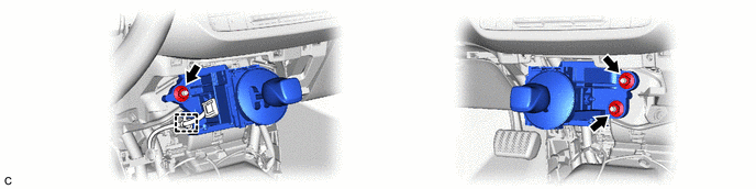
Disengage the clamp.
-
Remove the 3 nuts and separate the shift lock control unit assembly from the No. 1 instrument panel brace sub-assembly and No. 2 instrument panel brace sub-assembly.
-
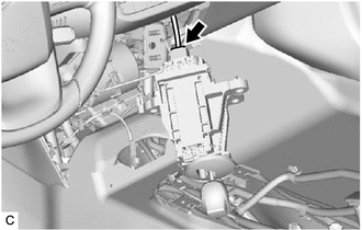
Disconnect the shift lock control unit assembly connector to remove the shift lock control unit assembly.
-