ELECTRONIC SHIFT LEVER SYSTEM, Diagnostic DTC:P1C8949
| DTC Code | DTC Name |
|---|---|
| P1C8949 | Park Pawl Motor Control System (Initially Drive) Internal Electronic Failure |
DESCRIPTION
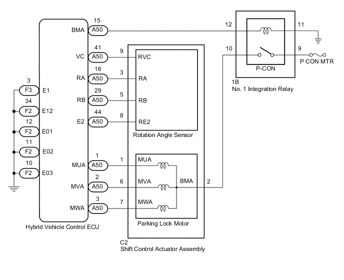
The shift control actuator assembly consists of a parking lock motor and rotation angle sensor.
The hybrid vehicle control ECU receives a P position switch signal from the P position switch (transmission shift main switch) and operates the parking lock motor through current control to engage and release the parking lock. The hybrid vehicle control ECU detects the motor rotation angle through signals from the rotation angle sensor and controls the timing of application of current to the coils of the parking lock motor.
If the hybrid vehicle control ECU detects a malfunction in the actuator system, it stores this DTC.
| DTC No. | Detection Item | DTC Detection Condition | Trouble Area | Warning Indicate | Memory |
|---|---|---|---|---|---|
| P1C8949 | Park Pawl Motor Control System (Initially Drive) Internal Electronic Failure | Malfunction of the power system, such as when the auxiliary battery is discharged, an open or short occurs in the P-CON relay, shift control actuator assembly (parking lock motor or rotation angle sensor) or wire harness, or an internal malfunction of the shift control actuator assembly (parking lock motor or rotation angle sensor). |
|
|
DTC stored |
CONFIRMATION DRIVING PATTERN
Tech Tips
After repairs have been completed, clear the DTCs and then check that the vehicle has returned to normal by performing the following All Readiness check procedure.
-
Turn the power switch on (IG).
-
With the brake pedal depressed, select neutral (N).
-
Push the P position switch (transmission shift main switch).
WIRING DIAGRAM
CAUTION / NOTICE / HINT
Note
-
Do not remove/install the auxiliary battery or disconnect the cable from the negative (-) auxiliary battery terminal before instructed.
-
After turning the power switch off, waiting time may be required before disconnecting the cable from the negative (-) auxiliary battery terminal. Therefore, make sure to read the disconnecting the cable from the negative (-) auxiliary battery terminal notices before proceeding with work.
PROCEDURE
-
CHECK DTC OUTPUT (HYBRID CONTROL)
-
Connect the GTS to the DLC3.
-
Turn the power switch on (IG).
-
Enter the following menus: Powertrain / Hybrid Control / Trouble Codes.
Powertrain > Hybrid Control > Trouble Codes -
Check if DTCs are output.
Result Result Proceed to None of the DTCs in the table below are output. A Any of the DTCs in the table below are output. B Priority Relevant DTC 1 P060647 Hybrid/EV Powertrain Control Module Processor Watchdog / Safety MCU Failure P060A29 Hybrid/EV Powertrain Control Module Monitoring Processor Signal Invalid P060A44 Hybrid/EV Powertrain Control Module Monitoring Processor Data Memory Failure P060A45 Hybrid/EV Powertrain Control Module Monitoring Processor Program Memory Failure P060A47 Hybrid/EV Powertrain Control Module Monitoring Processor Watchdog / Safety MCU Failure P060A49 Hybrid/EV Powertrain Control Module Monitoring Processor Internal Electronic Failure P06881F ECM/PCM Power Relay Sense Circuit Intermittent 2 P1C8F14 Park Pawl Motor Phase U Circuit Short to Ground or Open P1C9414 Park Pawl Motor Phase V Circuit Short to Ground or Open P1C9914 Park Pawl Motor Phase W Circuit Short to Ground or Open Tech Tips
Perform troubleshooting for higher priority DTCs first.
-
Turn the power switch off.
B 
GO TO DTC CHART (HYBRID CONTROL SYSTEM, ELECTRONIC SHIFT LEVER SYSTEM) for Hybrid Control System: Click here
GO TO DTC CHART (HYBRID CONTROL SYSTEM, ELECTRONIC SHIFT LEVER SYSTEM) for Electronic Shift Lever System: Click hereA 
-
-
CHECK FREEZE FRAME DATA (HYBRID CONTROL)
-
Connect the GTS to the DLC3.
-
Turn the power switch on (IG).
Tech Tips
Do not turn the power switch on (READY).
-
Enter the following menus: Powertrain / Hybrid Control / Trouble Codes.
Powertrain > Hybrid Control > DTC(P1C8949) > Freeze Frame DataTester Display BATT Voltage for Transmission Control System -
Read the freeze frame data of DTC P1C8949.
Result Result Proceed to The value of BATT Voltage for Transmission Control System is 9 V or more A The value of BATT Voltage for Transmission Control System is less than 9 V B -
Turn the power switch off.
B
REPLACE AUXILIARY BATTERY Click here
A
-
-
CLEAR DTC
-
Connect the GTS to the DLC3.
-
Turn the power switch on (IG).
-
Enter the following menus: Powertrain / Hybrid Control / Trouble Codes.
-
Clear the DTCs.
Powertrain > Hybrid Control > Clear DTCs -
Disconnect the GTS from the DLC3.
-
Turn the power switch off.
-
Leave the vehicle as is for 60 seconds or more.
Note
-
Do not connect the GTS.
-
Do not depress brake pedal.
-
Do not open/close any of the doors.
Result Proceed to NEXT -
NEXT
-
-
CHARGE AUXILIARY BATTERY
-
Charge the auxiliary battery.
Result Proceed to NEXT
NEXT
-
-
CHECK DTC OUTPUT (SIMULATION TEST)
-
Connect the GTS to the DLC3.
-
Turn the power switch on (IG).
Tech Tips
Do not turn the power switch on (READY).
-
Depress the brake pedal and select neutral (N).
-
Enter the following menus: Powertrain / Hybrid Control / Trouble Codes.
-
Check if DTCs are output.
Powertrain > Hybrid Control > Trouble CodesResult Result Proceed to P1C8949 is output A P1C8949 is not output B -
Turn the power switch off.
B
END (AUXILIARY BATTERY WAS INSUFFICIENTLY CHARGED)
A
-
-
CHECK HARNESS AND CONNECTOR (HYBRID VEHICLE CONTROL ECU - SHIFT CONTROL ACTUATOR ASSEMBLY)
-
Disconnect the A50 hybrid vehicle control ECU connector.
-
Disconnect the C2 shift control actuator assembly connector.
-
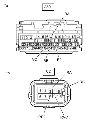
*a Front view of wire harness connector
(to Hybrid Vehicle Control ECU)
*b Front view of wire harness connector
(to Shift Control Actuator Assembly)
Measure the resistance according to the value(s) in the table below.
Standard Resistance (Check for Open) Tester Connection Condition Specified Condition A50-41 (VC) - C2-9 (RVC) Power switch off Below 1 Ω A50-16 (RA) - C2-3 (RA) Power switch off Below 1 Ω A50-29 (RB) - C2-5 (RB) Power switch off Below 1 Ω A50-44 (E2) - C2-8 (RE2) Power switch off Below 1 Ω Standard Resistance (Check for Short) Tester Connection Condition Specified Condition A50-41 (VC) or C2-9 (RVC) - Body ground and other terminals Power switch off 10 kΩ or higher A50-16 (RA) or C2-3 (RA) - Body ground and other terminals Power switch off 10 kΩ or higher A50-29 (RB) or C2-5 (RB) - Body ground and other terminals Power switch off 10 kΩ or higher A50-44 (E2) or C2-8 (RE2) - Body ground and other terminals Power switch off 10 kΩ or higher -
Reconnect the C2 shift control actuator assembly connector.
-
Reconnect the A50 hybrid vehicle control ECU connector.
Result Proceed to OK NG
NG
REPAIR OR REPLACE HARNESS OR CONNECTOR
OK
-
-
CHECK SHIFT CONTROL ACTUATOR ASSEMBLY (ROTATION ANGLE SENSOR)
-
Disconnect the A50 hybrid vehicle control ECU connector.
-
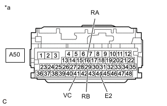
*a Front view of wire harness connector
(to Hybrid Vehicle Control ECU)
Measure the resistance according to the value(s) in the table below.
Standard Resistance Tester Connection Condition Specified Condition A50-41 (VC) - A50-16 (RA) Power switch off 10 kΩ or higher A50-41 (VC) - A50-29 (RB) Power switch off 10 kΩ or higher A50-41 (VC) - A50-44 (E2) Power switch off 590 to 670 Ω A50-16 (RA) - A50-29 (RB) Power switch off 10 kΩ or higher A50-16 (RA) - A50-44 (E2) Power switch off 10 kΩ or higher A50-29 (RB) - A50-44 (E2) Power switch off 10 kΩ or higher -
Reconnect the A50 hybrid vehicle control ECU connector.
Result Proceed to OK NG
NG
REPLACE SHIFT CONTROL ACTUATOR ASSEMBLY Click here
OK
-
-
CHECK HARNESS AND CONNECTOR (HYBRID VEHICLE CONTROL ECU - BODY GROUND)
-
Disconnect the F2 hybrid vehicle control ECU connector.
-
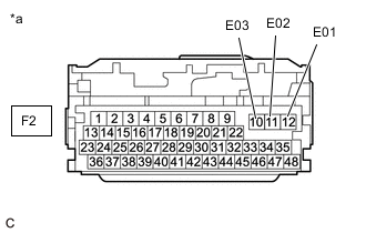
*a Front view of wire harness connector
(to Hybrid Vehicle Control ECU)
Measure the resistance according to the value(s) in the table below.
Standard Resistance (Check for Open) Tester Connection Condition Specified Condition F2-12 (E01) - Body ground Power switch off Below 1 Ω F2-11 (E02) - Body ground Power switch off Below 1 Ω F2-10 (E03) - Body ground Power switch off Below 1 Ω -
Reconnect the F2 hybrid vehicle control ECU connector.
Result Proceed to OK NG
NG
REPAIR OR REPLACE HARNESS OR CONNECTOR
OK
-
-
CHECK SHIFT CONTROL ACTUATOR ASSEMBLY
-
Check that the parking brake is applied.
-
Disconnect the C2 shift control actuator assembly connector.
-
Remove the 3 shift control actuator bolts.
Tech Tips
-
Slightly pull the shift control actuator assembly from the hybrid vehicle transaxle assembly.
-
Reconnect the C2 shift control actuator assembly connector.
-
Release the brake pedal and turn the power switch on (ACC).
Note
The shift control actuator assembly may operate if the power switch is turned on (IG) or (READY). Do not turn the power switch on (IG) or (READY) during this inspection to prevent the shift control actuator assembly from operating while in contact with the splines.
-
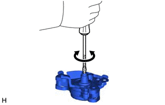
Using a screwdriver with its tip wrapped with protective tape or a piece of cloth, rotate the shaft.
Note
-
During this inspection, make sure to use a screwdriver with its tip wrapped with protective tape or a piece of cloth to prevent the splines of the actuator from being damaged.
-
The shift control actuator assembly cannot be disassembled.
-
Confirm that the shaft of the shift control actuator assembly rotates smoothly.
OK The shaft of the shift control actuator assembly rotates smoothly. -
Measure the voltage according to the value(s) in the table below.
Note
When measuring the voltage, turn the shift control actuator assembly slowly.
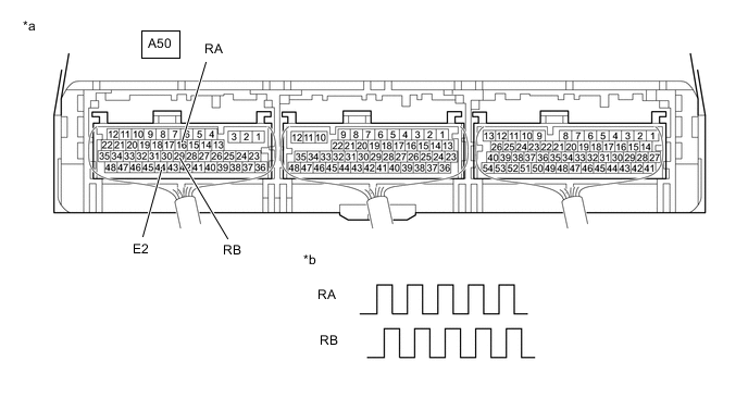
*a Component with harness connected
(Hybrid Vehicle Control ECU)
*b Output Waveform while Splines of Shift Control Actuator Assembly being Rotated (Example) Standard Voltage Tester Connection Condition Specified Condition A50-16 (RA) - A50-44 (E2) Power switch on (ACC), shaft of shift control actuator assembly being rotated 0 to 1.5 V ←→ 4 to 5.5 V A50-29 (RB) - A50-44 (E2) Power switch on (ACC), shaft of shift control actuator assembly being rotated 0 to 1.5 V ←→ 4 to 5.5 V
-
-
Turn the power switch off.
Result Proceed to OK NG
OK
REPLACE HYBRID VEHICLE CONTROL ECU Click here
NG
REPLACE SHIFT CONTROL ACTUATOR ASSEMBLY Click here
-